
Direct answer: read a P&ID by checking its revision and legend, identifying tagged equipment and instruments, tracing each connection through junctions and continuation references, and recording the conditions that affect flow. A line crossing, a symbol or a familiar tag abbreviation is not enough to establish meaning without the drawing’s conventions.
This beginner exercise produces a small connection worksheet. It is useful before manual equipment design, a design review, or an AI-assisted interpretation.
On this page: open the example drawing, follow three connections, and check your reading.
Start with a drawing you can follow
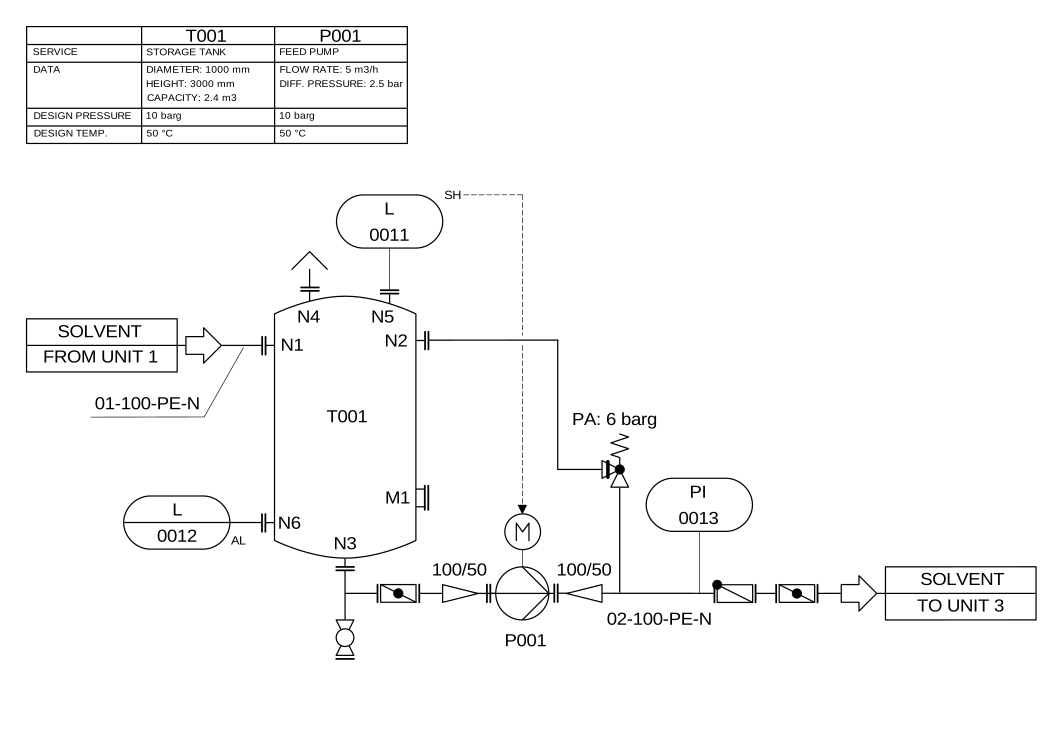

Begin with three visible objects: T001 is the storage tank, P001 is the feed pump, and N1–N6 identify tank nozzles. The small equipment table helps identify T001 and P001. A nozzle label is not a separate equipment tag.
Step 1: establish which drawing you are reading
Record the drawing number, revision, sheet number, title, approval status and the legend or notes that govern it. Keep related sheets and the equipment/instrument lists available. If two sheets have conflicting revisions, identify that conflict before joining their connections.
ISO 10628-1 covers the content and representation of process diagrams. Its scope does not mean every customer PDF follows identical naming or symbols. The project’s approved conventions remain necessary.
Step 2: identify objects using both symbol and tag
For each item, record its visible tag, symbol class, page location and the legend entry supporting your interpretation. Keep uncertain text and uncertain symbol identity separate. A clear tag beside an unclear symbol does not resolve the device type.
Do not copy tag expansions from another plant’s drawing without checking. A letter combination may follow a standard convention, a company convention or a project-specific exception. The worksheet should preserve the original text alongside the interpretation.
Step 3: trace one connection at a time
- Choose one tagged item and follow its process line to the next item or continuation.
- At every crossing, inspect the drawing’s junction convention. Do not automatically connect every intersecting stroke.
- Record line identity and any specification break or annotation affecting that segment.
- For an off-page connector, locate the referenced sheet and matching continuation. Mark it unresolved if either is absent.
- Use explicit arrows and documented process context for direction. Do not infer flow simply because the drawing reads from left to right.
The DEXPI P&ID 1.4 piping-segment model distinguishes items, connections, source/target references and flow-direction information. It is a useful example of why these facts should be recorded separately; this worksheet is not a claim that your PDF is DEXPI-compliant.
Step 4: trace three routes in the example
| Route to locate | What to record | What remains unresolved |
|---|---|---|
| Unit 1 → T001/N1 | Follow the continuous inlet line, its arrow and label 01-100-PE-N. | The upstream equipment beyond this sheet. |
| T001/N3 → P001 inlet | Follow the tank outlet through each intervening symbol; note every branch. | Any symbol meaning that lacks a confirmed legend. |
| P001 discharge → Unit 3 | Follow line 02-100-PE-N to the external boundary; record the return branch separately. | The downstream equipment and operating conditions. |
These are route summaries. In your detailed worksheet, split a route at each identified device or branch. Do not skip the return connection toward T001/N2 simply because you are following the main path.
Next locate the dashed relationship from the level-related item labelled L 0011, with SH beside it, toward the motor. Keep this instrument relationship separate from the solvent pipe sequence. The diagram does not supply a complete control cause-and-effect description.
Step 5: produce a reviewable worksheet
Use columns for source item, destination item, line/tag reference, page location, direction evidence, applicable condition, unresolved question and reviewer. Keep “unreadable,” “not shown” and “contradictory” as different findings. They require different follow-up.
A reviewer should be able to return to the drawing location for every accepted connection. The exercise is complete when each in-scope path is either supported or explicitly unresolved, not when every row has been filled with a guess.
Check your reading before moving on
- Does the dashed instrument relationship add another solvent pipe?
- Does the “TO UNIT 3” arrow identify all downstream equipment?
- Can the return branch be omitted from the connection record?
Show the answers
No to all three. Record the instrument relationship separately; resolve the off-page continuation using its referenced documents; retain the return branch as its own connection. A good reading record preserves uncertainty instead of silently inventing the missing facts.
What a P&ID does not supply by itself
Do not assume it contains all elevations, component envelopes, mating faces, maintenance clearances or a complete mechanical BOM. Those facts must come from the controlled design package before a native assembly can be generated and checked.
Continue with P&ID understanding beyond OCR, part-number and configuration mapping, or the P&ID-to-3D input requirements.
Try a complete illustrated example
Work through the tank-and-pump P&ID exercise, with an attributed full-size drawing. Trace the material path, record its branches, and keep the instrument signal separate from the pipe network.
Scope: reviewed 17 September 2026 against the attributed drawing and cited references. This is a reading exercise, not an operating procedure, a universal symbol dictionary or an engineering approval of a real process.
MST Engineering Intelligence. “How to Read a P&ID: Symbols, Tags and Connections.” MST Engineering Intelligence. Updated 2026-09-17. https://mst-us.ai/how-to-read-a-pid/
CUSTOMERS · PARTNERS · INVESTORS
Talk to the engineering team.
Bring a non-confidential P&ID question, pilot boundary or technical diligence request. Protected engineering material is exchanged only after identity, NDA and scope review.
Operated by MOORE SOLUTION TECHNOLOGY PTE. LTD. · Singapore UEN 202315239E