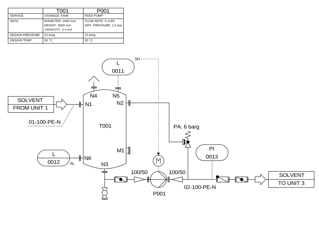
To trace a P&ID, follow physical connections and instrument signals as separate paths. Record the equipment and nozzle at each end, the evidence for direction, and any branch whose purpose needs confirmation. This worked exercise uses a storage tank and feed pump to turn a drawing into a small connection worksheet.
Start with the P&ID reading introduction if equipment tags and instrument bubbles are new to you. For this exercise, keep the diagram open beside your notes.

1. Make an equipment and boundary register
Find T001 in the drawing and in the small equipment table. Both refer to the storage tank. Find P001 and its feed-pump description. Keep these equipment tags separate from nozzle labels N1–N6 and instrument identifiers 0011–0013.
Write two external boundaries: solvent from Unit 1, and solvent to Unit 3. The off-page arrows establish the illustrated route across this sheet; they do not supply the missing drawings, operating procedures or every possible operating state.
2. Trace the main material path
- Start at the left-hand “FROM UNIT 1” boundary. Follow line
01-100-PE-Nto tank nozzle N1. - Find the tank’s bottom nozzle N3. Follow its connected line toward the pump inlet, identifying the intervening symbols with the applicable legend.
- Continue through P001 to the discharge line labelled
02-100-PE-N, then to the “TO UNIT 3” boundary. - Mark every branch encountered, including the downward branch near N3 and the connection returning toward nozzle N2. A branch must not disappear from the worksheet merely because it is outside the main route.
Use one row per connection between identifiable endpoints. For example: “Unit 1 boundary → T001/N1; evidence: continuous line and inlet arrow; line label: 01-100-PE-N.” Copy the complete line identifier before trying to decode its fields; the project’s numbering specification supplies their meaning.
3. Trace the instrument path separately
Locate the dashed connection from the level-related item labelled L 0011, with SH beside it, toward the pump motor. Record that this is a distinct drawn relationship. Do not add it to the solvent pipe sequence.
Then find L 0012 near N6 and PI 0013 on the discharge side. Record each exact label, its drawn attachment and the legend entry that explains it. Instrument notation depends on the documented convention; this image’s author describes EN 62424 instrumentation notation.
The picture alone does not provide a complete cause-and-effect table. Whether a signal starts, stops, alarms, trips or permits equipment operation must be verified against the relevant control documentation.
4. Keep connections and direction evidence distinct
The DEXPI information model represents segment connections, source/target references and flow classification as separate attributes. Use the same discipline in your worksheet: identifying two connected objects does not by itself establish every operating direction or condition.
Inspect the branch between the pump discharge and T001/N2. Record the displayed symbol and the text PA: 6 barg, then list the information needed to interpret that branch. Do not turn the label into a recommended setting. Likewise, the equipment table’s design pressure and temperature are different facts from a measured operating condition.
5. Check your worksheet against the picture
- Every equipment tag points back to one identified object.
- The main route reaches both external boundaries and includes T001/N1, T001/N3 and P001.
- Branches and instruments remain visible as separate records.
- Each direction statement cites an arrow, explicit annotation or another identified source.
- Unexplained symbols, line-code fields and control actions stay marked as unresolved.
Your result should be a reviewable reading record. It is not an operating instruction or a validated digital model. Ask a second reader to reproduce one route using only your references; disagreements identify where the worksheet needs more evidence.
Continue and verify the sources
Next, read why P&ID understanding goes beyond OCR and the part identity and BOM exercise.
- Original diagram, author and licence.
- DEXPI 1.4: PipingNetworkSegment.
- ISO 10628-1: diagram specification scope.
Reviewed 17 September 2026. This is a diagram-reading exercise. Use the controlled project legend and approved engineering documents for a real installation.
MST Engineering Intelligence. “P&ID Flow and Instrument Signals: A Worked Reading Exercise.” MST Engineering Intelligence. Updated 2026-09-16. https://mst-us.ai/pid-flow-and-instrument-signals/
CUSTOMERS · PARTNERS · INVESTORS
Talk to the engineering team.
Bring a non-confidential P&ID question, pilot boundary or technical diligence request. Protected engineering material is exchanged only after identity, NDA and scope review.
Operated by MOORE SOLUTION TECHNOLOGY PTE. LTD. · Singapore UEN 202315239E