From a process diagram to a complete 3D equipment assembly.

A P&ID tells you what must connect. MST plans where the components go and how they fit together, then builds an editable SOLIDWORKS assembly from your approved parts and engineering rules. Start with configured semiconductor gas equipment and a result your engineers can inspect and develop further.

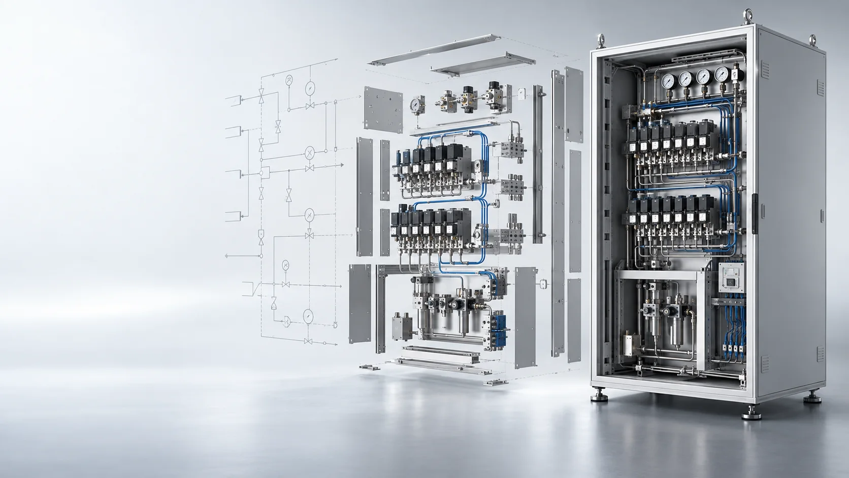
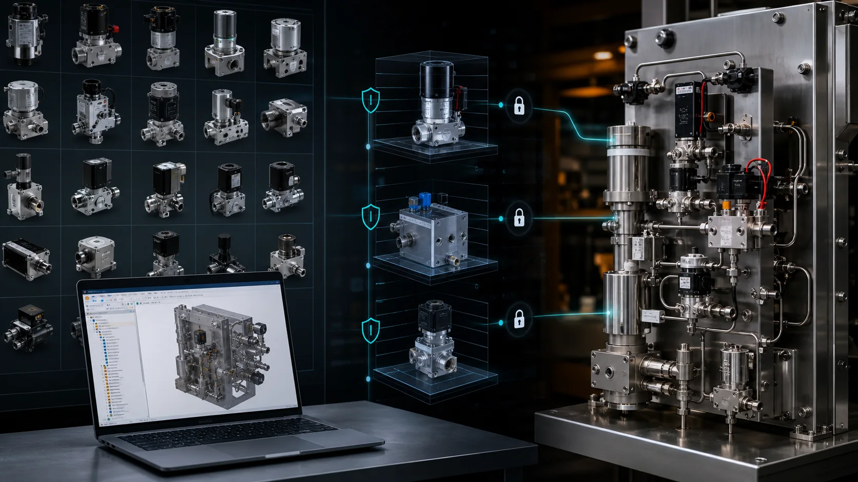
Concept illustration showing a process diagram, an exploded component layout and an assembled semiconductor gas-equipment cabinet
Concept illustration: process intent, component layout and an equipment assembly.

SEE THE ASSEMBLY TAKE SHAPE

How much of a semiconductor gas-delivery system can AI design?

Its valves, flow controllers, fittings and mounting interfaces have to work together as one physical assembly. MST brings process requirements, approved components and layout decisions into that equipment-design workflow.

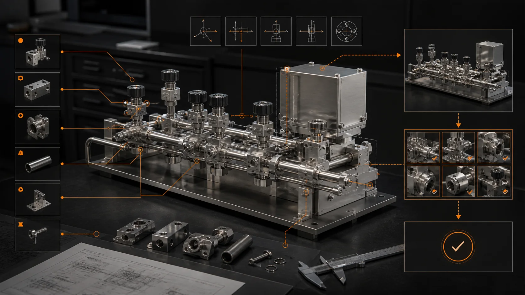
This recording lets you see one part of that work: native components being assembled in SOLIDWORKS. Watch the assembly take shape, then explore how the execution stage connects to the wider P&ID-driven workflow below.

Discuss a demo for your equipment

A short description of your equipment and repetitive design work is enough to start. No drawings are needed.

See what the recording demonstrates

92-second recording, without audio. It shows the assembly-execution stage; it does not measure the full P&ID-to-delivery workflow or establish a new acceptance result.

Open MP4 · Watch on YouTube

P&ID → OPTIMIZED PHYSICAL ARRANGEMENT

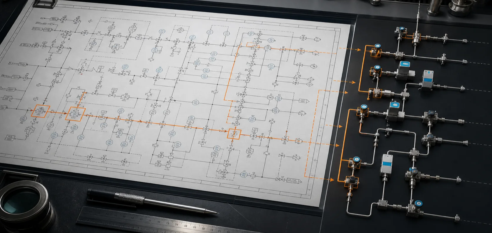
A P&ID defines what connects. MST solves where every approved component should go.

Within a declared engineering boundary, two coupled solvers search for a compact, feasible physical result. A layout change reshapes the routes; an infeasible route sends the layout back for another candidate.

CONTROLLED INPUT P&ID INTENT Approved PDM models · interfaces · rules · objectives
ENGINEERING RESULT NATIVE .SLDASM Build · reopen · read back · verify
HARD CONSTRAINTSinterfaces · collision · bend rules · access · mounting · safety DECLARED OBJECTIVESsmaller envelope · shorter routes · fewer fittings · lower complexity

Optimization boundary: “Optimized” means selected against the customer-approved objectives, hard constraints, search space and stopping criteria. It is not a claim of a universal global optimum, and engineers retain release authority. Read the P&ID-to-assembly answer

FROM YOUR PARTS TO YOUR NEXT DESIGN

Your next design starts with the parts you already use.

Bring your P&ID, approved components and engineering rules. MST connects them into a physical layout and an editable SOLIDWORKS assembly.

For configured semiconductor equipment, with your approved models and rules. Your engineers approve the result for release.

Concept illustration of a component library connected to an equipment assembly
Concept illustration · approved component library

01 / REUSE

Reuse your proven parts.

Start with your approved valves, flow controllers, fittings and native models. Keep part identity and revisions tied to the design.

Models come from your authorized PDM scope or a controlled export.

Explore model reuse
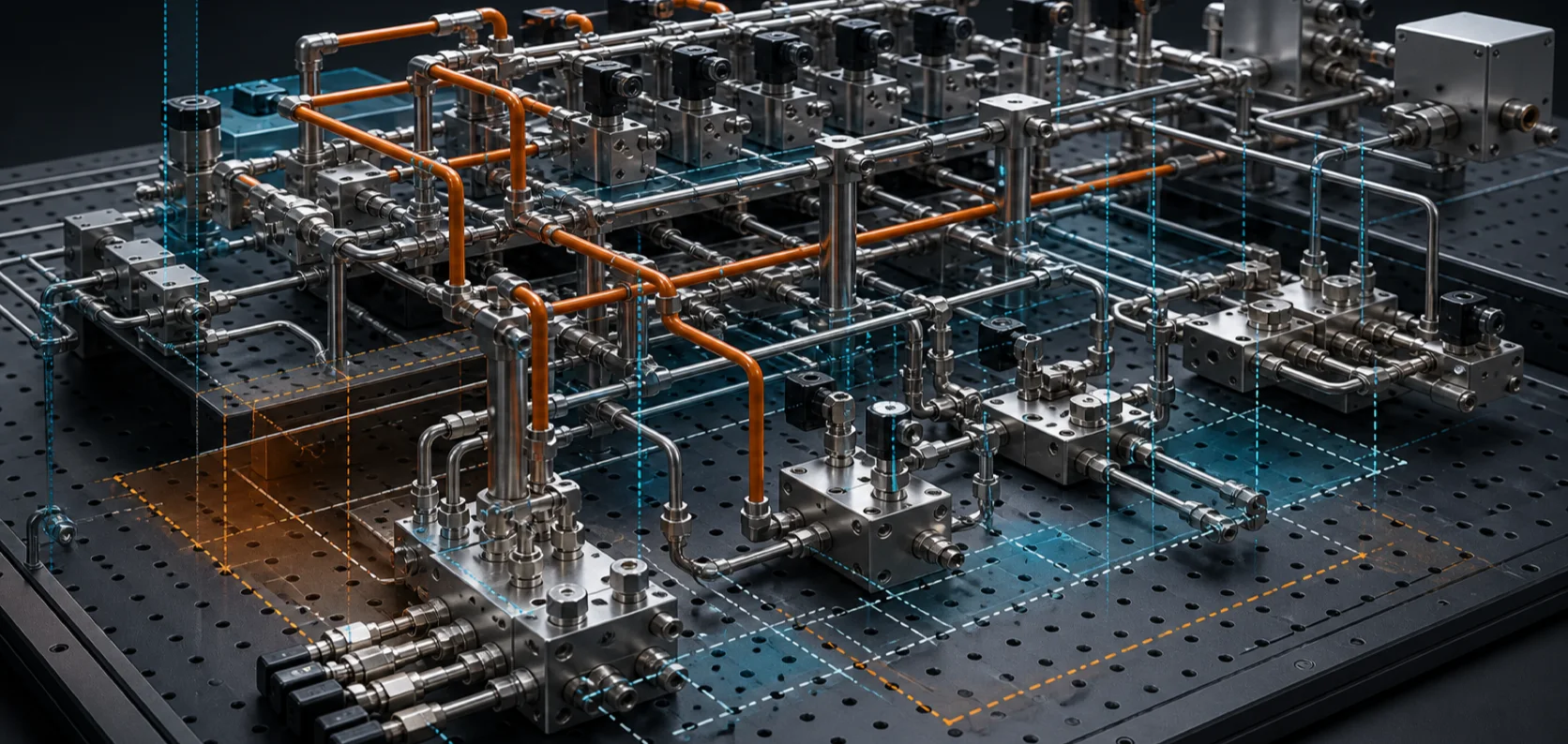
Concept illustration showing component positions, connecting routes and space constraints
Concept illustration · component layout and connections

02 / ARRANGE

Make the parts fit together.

A smaller cabinet changes more than component positions. MST plans placement and connections together, using the interfaces, keep-outs and access rules defined for the task.

Explore layout and routing
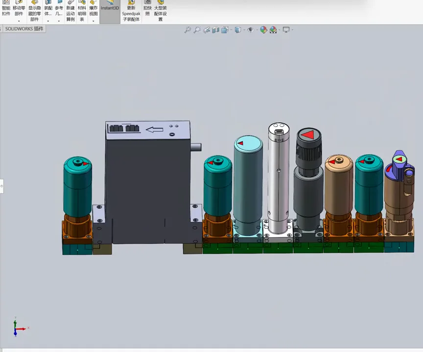
Actual native SOLIDWORKS assembly shown in MST’s published 92-second recording
Actual recording frame · native SOLIDWORKS assembly

03 / KEEP DESIGNING

Open it. Inspect it. Keep designing.

The output is a native, editable SOLIDWORKS assembly. Your engineers can inspect the components and continue developing the design.

This frame comes from the published assembly-execution demo.

Watch the assembly take shape
Explore the six engineering steps
IMPLEMENTATION BOUNDARYThis is an implemented controlled workflow, not a claim of universal CAD or PDM autonomy. Each deployment binds an authorized model scope, declared engineering rules, optimization objectives, a target SolidWorks environment and engineer release authority. MST resolves existing models from the customer’s authorized PDM/model-library and does not regenerate qualified valves, MFCs, blocks or fittings. Review the verification method.
  1. Recover intent from P&ID PDF

    Tags, symbols, linework, connections, flow direction, conditions and source evidence become typed observations.

  2. Build a directed engineering graph

    The graph preserves direction and conditional state instead of reducing the drawing to undirected connectivity.

  3. Bind customer PDM and geometry truth

    Authorized BOM/SAP/PDM identity, revision and lifecycle state are joined to the exact native model and its B-Rep interfaces.

  4. Couple layout and routing solvers

    Search component XYZ, orientation and interface placement together with feasible paths, fittings, layer changes and keep-outs against declared compactness and engineering objectives.

  5. Compile deterministic Assembly IR

    Create a versioned plan for parts, poses, mates, routing tasks, checks and evidence obligations.

  6. Execute and reverse-prove in SolidWorks

    Within the declared controlled scope, MST creates a native .sldasm, reopens it and reads back the checks configured for the declared acceptance scope. Unverified items remain explicit; customer engineering release is still required.

Concept illustration connecting components, assembly interfaces and an engineering review
Concept illustration · tracing components and checks

ENGINEERING REVIEW

See what was checked.

MST reopens the assembly and reads back the checks configured for your task. See which inputs produced the result and which checks still need attention.

Unverified items remain explicit. Your engineers retain release authority.

Review the verification method
From P&ID intent to physical connections

Why PDF-to-assembly is the barrier

Reading native SolidWorks models is only one layer.

The difficult work is maintaining accountable meaning across document perception, directed topology, enterprise part identity, real interfaces, continuous 3D physical layout, SolidWorks execution and round-trip verification. Starting with an already-clean assembly skips most of that chain.

NO GUESSING

Fail closed on missing truth

Unresolved identity, interface or rule evidence blocks execution or requires explicit engineering approval.

PHYSICAL CONSEQUENCES

A routing change changes the design

Layer changes become real blocks, bridges, elbows, tubes and BOM consequences—not a line moved on screen.

REVERSE PROOF

Trace the declared acceptance scope

Review how P&ID requirements map to selected physical paths and the available component, mate and interface facts. A missing check is not a pass.

How the assembly plan reaches CAD

02 / ASSEMBLY IR

One compiler contract.
Multiple CAD adapters.

The physical solution is represented before any CAD API is called. Assembly IR v1 separates engineering meaning from vendor-specific execution while preserving deterministic instructions and evidence obligations.

DECLARED PHYSICAL RESULTcomponents + interfaces + connections + poses + evidence
UNIVERSAL ASSEMBLY COMPILERAssembly IR v1insert · pose · align · mate · fix · route · verify
CURRENT CONTROLLED EXECUTION PATHSolidWorks Adapter
ARCHITECTURAL EXTENSIONFreeCAD Adapter
ADAPTER CONTRACTOther CAD systems
What the verification record contains

03 / VERIFIED ENGINEERING INTELLIGENCE

AI proposes.
Engineering authority decides.

The MST Engineering Intelligence Kernel governs task orchestration, evidence, approvals, replay and regression. Learned patterns from approved historical assemblies may rank candidates or propose rules; only deterministic, versioned and approved authority may affect production compilation.

01Input identityP&ID · BOM · boundary · library · Rulepack · hashes
02Deterministic compileSame approved inputs and versions → same Assembly IR
03Real execution facts.sldasm · mates · rebuild · geometry · interfaces
04Explicit verdictAUTO_PASS · PASS_WITH_ENGINEER_REVIEW · FAIL_CLOSED · CANNOT_VERIFY

PRODUCT QUESTIONS

What your team needs to know.

Licensed software for your engineering team. Reuse your approved model library across supported, configured assembly tasks. Deployment, initial library enablement and acceptance criteria are scoped to your environment.

Can AI do mechanical design?

MST automates bounded mechanical assembly tasks with authorized inputs, supported part families, declared engineering rules and acceptance checks. It does not replace engineers or claim arbitrary whole-machine design.

Can MST turn a P&ID into a SolidWorks assembly?

Within its configured scope, MST connects P&ID equipment and connection requirements to approved models, constrained layout and routing, then directs SolidWorks to create an editable native assembly. New part families or unresolved interfaces may need onboarding or engineering review.

Does MST use our own PDM and CAD models?

Yes. MST uses customer-approved native models from an explicitly authorized PDM/model-library scope or controlled export. It does not regenerate qualified parts. The public website does not access customer PDM.

How is the assembly checked?

MST reopens the native assembly and reads back the checks configured for the declared acceptance scope. The review must identify which component, mate, rebuild, connection or spatial checks were performed and which remain unverified. Customer engineering approval is still required for production release.

Can I upload drawings or CAD files to Ask MST?

No. Public Ask MST is a human-follow-up inquiry channel. It accepts no files, connects to no customer systems and executes no engineering tasks. The public LLM adviser is not enabled. Protected data requires a separately authorized deployment process.

Brand illustration of engineers reviewing a process-equipment design
Brand illustration · engineer-led design review

START WITH A DEFINED TASK

Built around your equipment and engineering rules.

Start with supported semiconductor gas equipment. Agree on the model library, design constraints and acceptance checks for your environment.

New equipment categories need their own configured libraries, rules and validation.

Explore deployment
Supported scope and release responsibilities

04 / CURRENT CONTROLLED SCOPE

A narrow contract is stronger than unlimited autonomy.

The current controlled scope is modular semiconductor process-equipment assembly under authorized libraries, approved Rulepacks and defined engineering constraints. The bounded execution contract requires no engineer operation during the run; customer engineering approval and production release remain required outside it.

P&ID/BOM-driven assembly tasksImplemented within controlled inputs
Arbitrary whole-machine autonomyNot claimed
Approved native component modelsCustomer libraries remain authoritative
Regenerating arbitrary qualified partsNot claimed
Native SolidWorks assembly executionImplemented: create, reopen and inspect within the declared controlled scope
FreeCAD or universal CAD production supportArchitecture only; not claimed
Fail-closed evidence gatesPASS / FAIL / CANNOT_VERIFY
Production release without customer authorizationNot permitted
Where the product is heading next

ONE APPROACH · EXPANDING APPLICATIONS

Mechanical assembly first. More engineering deliverables next.

The product is designed around reusable customer models, interfaces, engineering rules and governed tool execution. Process-equipment assembly is the first application, not the limit of the product vision. Each new industry needs its own configured libraries, constraints and acceptance checks.

Planned modules: engineering drawing generation and manufacturing/detail drawings. These are expansion directions, not capabilities demonstrated by the current assembly recording or a release-date commitment.

START WITH YOUR EQUIPMENT

What would you like to stop rebuilding by hand?

Tell us what equipment you design, which task takes the most time and whether you use SOLIDWORKS. We will review fit and discuss a live demonstration.

Discuss your equipment