

← Drawing and 3D printing tutorials
To 3D print from a 2D engineering drawing, first build and check a three-dimensional model. A PDF, scan or flat CAD view does not by itself specify a printable volume. Use dimensions and views to resolve the shape, export a format your receiving software accepts, inspect the sliced result, then measure the trial print against the drawing.
This guide follows a simple locating-block exercise from drawing requirements to an inspection checklist. It helps you decide what is missing before asking a modeler or printing service for a quote.
Jump to: Check the drawing · First-prototype brief · Worked block example · Model-to-print handoff · Compare quotes · Common questions · Discuss a model task
Can your drawing define the whole part?
- A dimensioned multi-view drawing: compare front, top, side and section views. Identify overall dimensions, holes, steps, wall thicknesses and features hidden in one view.
- A single closed DXF outline: a constant-thickness plate may be possible when thickness is separately specified. Follow the DXF-to-solid exercise. A silhouette alone does not establish recess depths or internal cavities.
- A scanned PDF or photograph: use written dimensions as the design requirements. Image size, perspective or scan distortion can make traced distances unreliable. Record uncertain geometry and request clarification.
Keep the original file, drawing number, revision and units. Make a short missing-information list before modeling. For example: “Hole shown as a circle in the top view; no depth or through-hole note.” Both a blind hole and a through-hole fit that view, but they produce different parts. Do not silently choose one.
A first-prototype brief you can reuse
If you are developing your first physical product or preparing a customer’s first custom part, decide what the sample must teach you. An appearance model, a fit-check sample and a functional test part can need different materials, accuracy and review. A sketch with missing dimensions still needs design decisions before it becomes a complete modeling brief.
Copy these fields into your own project note. Use a non-confidential summary for an initial conversation; share drawings only through an agreed channel.
- Purpose: what will this sample demonstrate or test, and what decision will follow?
- Available input: drawing or CAD type, revision, units, and which views and dimensions exist. List missing information separately.
- Quantity and timing: how many samples you need and your requested delivery date. Ask the provider to confirm feasibility.
- Critical checks: dimensions, mating features or clearances that matter. Agree tolerances and how to measure them; do not leave the provider to infer them.
- Material and process: what is specified, what is still open, and any relevant conditions of use. Ask the provider which choices are appropriate.
- Digital delivery: required CAD application/version, geometry or native files, and the edit you must be able to make later. See the file-delivery checklist.
- Physical delivery: whether printing, finishing, inspection and shipping are included or handled separately.
- Approval and changes: who approves the model before printing, which revisions are included, and how additional work is priced.
Example brief for the exercise below: one locating block, revision A, millimeters, 60 × 30 × 10 mm with two diameter-5 mm through-holes at the specified centers. Purpose: review shape and later change the thickness to 12 mm in the agreed CAD application. Request separate modeling and sample-printing scope. Material, fit tolerances and delivery date remain open decisions; this brief is not ready for a functional acceptance test until those are resolved.
Separate design work from manufacturing in the request. For example, Xometry’s product-idea guidance asks for a 3D CAD file to start its quote workflow and directs design needs to a services directory. Confirm your chosen provider’s requirements before uploading or paying.
Worked example: a two-hole locating block
Teaching example, not an MST-generated or printed result. Assume a rectangular block with no chamfers, recesses or other features. Use millimeters. In the top view, place the origin at the lower-left corner, X along the 60 mm edge and Y along the 30 mm edge. Thickness extends 10 mm in Z. Both holes run through that thickness.
- Envelope: 60 × 30 × 10 mm.
- Hole A: diameter 5 mm, center X = 15 mm, Y = 15 mm.
- Hole B: diameter 5 mm, center X = 45 mm, Y = 15 mm.
- Derived check: center-to-center distance is 30 mm; each center is 15 mm from its nearest short end.
- Create the rectangular base from the stated dimensions, then add the two through-holes using the specified centers. Keep the dimensions easy to inspect in the working CAD document.
- Inspect top, side and section views. Confirm there are two openings through the full thickness, not shallow pockets or raised cylinders.
- Record the measured envelope, hole diameters and center spacing in the CAD model. Reopen the saved working file and repeat these checks.
- Export a separate print handoff. In the receiving software, check the envelope is still 60 × 30 × 10 mm before any intentional scaling or reorientation.
- Inspect sliced layers through both holes. After a trial print, record actual measurements separately from nominal dimensions. Agree tolerances and fit requirements before deciding whether the result passes.
If the envelope changes at export/import, investigate units and scale first. If the envelope is right but a hole is missing, inspect the modeled feature and the slice preview. If the digital checks pass but the physical fit fails, investigate printing, material, orientation and post-processing with the print provider. These observations locate different problems; they should not all be labeled a conversion failure.
What should you send to a 3D printing service?
Ask which model formats the service accepts and whether it offers modeling from drawings. Send the drawing revision and units with the model, identify important dimensions, and explain whether you need a visual prototype, fit check or functional part. Do not assume file acceptance includes a design review.
Use the STEP, STL and 3MF guide to separate the editable engineering master from the print handoff. Mesh export settings affect how curves are approximated. SOLIDWORKS explains the tradeoff between mesh resolution and file size in its model-preparation guide.
Before printing, review dimensions, body count, orientation, supports, thin features and the layer preview in the chosen process. Use that printer/material provider’s design guidance; one universal minimum wall thickness or hole allowance would be misleading. A successful slice does not establish strength or fit. See Formlabs’ printability guidance for an example of process-specific preparation.
How to compare prototype quotes
Give each provider the same revision and brief. Compare what is included before comparing totals:
- Modeling: creating or repairing CAD, resolving missing dimensions, and the number of review rounds.
- Files: exact formats, native dependencies, agreed editing capability, and rights to use and modify the delivered files.
- Manufacturing: process, material, quantity, orientation requirements, supports and finishing.
- Checks: who reviews the model, which physical dimensions will be inspected, and what evidence you receive.
- Commercial scope: price, payment stages, exclusions, shipping, applicable taxes, and the cost of changes or a reprint.
- Schedule: when work starts, approval milestones, and whether a delivery estimate includes model preparation and shipping.
For example, a quote for printing an already approved mesh cannot be compared directly with a quote that includes rebuilding your drawing, supplying editable CAD and inspecting the sample. Mark missing items as “not confirmed” and ask for clarification. Keep the approved revision and the final scope with the quote.
Common questions
Can I convert a PDF drawing directly to STL?
A flat drawing needs a modeling interpretation before it becomes a three-dimensional surface. Renaming the extension will not add thickness, hidden features or missing dimensions. A vector PDF and a scan also contain different kinds of information. First establish which geometry the source actually defines.
Will an attractive model necessarily print correctly?
No. It can have the wrong units, missing cavities, insufficient wall thickness for the process, or features that need support. Check the engineering model, exported file, sliced layers and physical result as separate stages.
Where can MST help?
The MST drawing-to-model module brings 2D drawing views and reconstructed geometry together for engineering review. Start by describing your drawing type and intended model use. Input compatibility, editable output and any print-file handoff must be agreed for your case. This article does not demonstrate MST STL/3MF export, slicing or a physical print.
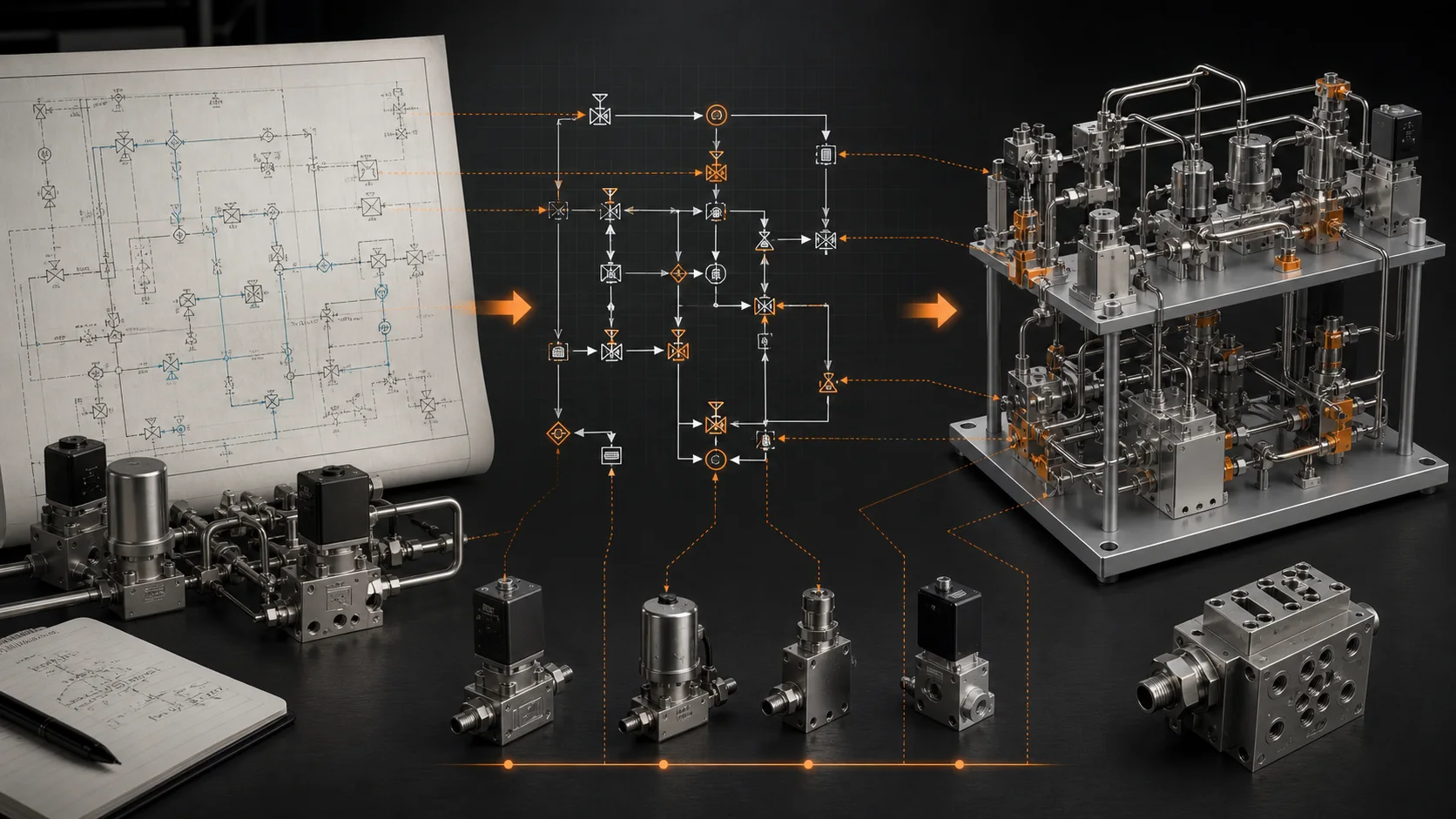
The 2D reconstruction workflow is separate from assembling approved equipment models from a P&ID. A full equipment assembly is not automatically a printable single part. Use the short task outline below for a first conversation.
Discuss one drawing-to-model task with MST
You can begin with your question and an email address. Describe the drawing type, the result you need and the change you expect to make later. You do not need to attach drawings or prepare a presentation for this first message.
Example message: “I have dimensioned 2D drawings for a small mechanical part. I need a model for prototype review, and I will need to change its thickness later in SOLIDWORKS. Can you explain whether MST fits this task, what inputs you would need, and how an evaluation would be scoped and priced?”
MST first reviews whether the task fits the product. If an evaluation is appropriate, agree the sample, supported input and output, engineering checks, responsibilities, fees and schedule before paid work begins. Printing and manufacturing need a separately confirmed scope. The drawing-to-model example shows the current module; it does not establish a turnaround time or accuracy guarantee for your drawing.
Ask about your drawing-to-model task. Keep the message non-confidential; arrange file sharing only after scope and confidentiality have been agreed.
Reviewed 7 October 2026. Original teaching workflow and hypothetical dimensions; no CAD execution, print test, material qualification or time-saving measurement was performed for this publication. Engineers and the print provider must agree acceptance criteria for the actual application.
MST Engineering Intelligence. “2D Drawing to 3D Printing: Model Preparation and Checks.” MST Engineering Intelligence. Updated 2026-10-07. https://mst-us.ai/2d-drawing-to-3d-printing/
CUSTOMERS · PARTNERS · INVESTORS
Talk to the engineering team.
Tell us about your 2D drawings and the 3D models your team needs. Start with a non-confidential description so we can discuss a relevant demonstration.
Operated by MOORE SOLUTION TECHNOLOGY PTE. LTD. · Singapore UEN 202315239E