
Direct answer: check the component’s referenced configuration, that configuration’s BOM part-number setting, the BOM column definition and the table’s grouping rules. A filename, configuration name, custom property and displayed BOM part number can be different values. Decide which field owns the approved part identity before changing the table.
This tutorial helps a CAD engineer map a small native model library to a reviewable BOM. The worked example uses invented part numbers and desktop SOLIDWORKS configuration behavior; 3DEXPERIENCE-connected workflows can use different options.
Have a PDF drawing instead of the native model? Start with extracting and checking the drawing’s BOM. For a SOLIDWORKS export, continue with the configuration checks below, including a before/after configuration-change example.
Step 1: identify the four values
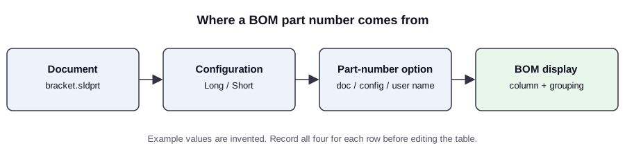
- Document: the model file being referenced.
- Configuration: the particular variant used by an assembly component.
- Approved part identity: the part number and revision controlled by your engineering/PDM process.
- BOM display: the value the relevant table column actually shows.
Keep a mapping row containing all four. If a team has only renamed a file to look like a part number, it has not necessarily changed the configuration’s BOM setting or the table’s property source.
Step 2: inspect the configuration setting
In ConfigurationManager, open the relevant configuration’s Properties and inspect its Bill of Materials options. The official configuration documentation describes document-name, configuration-name and user-specified-name choices, plus the parent option for derived configurations. Available behavior depends on the environment.
Choose the option that agrees with the team’s part-master policy. Do not create a new part identity just to make a table look tidy. Record the configuration and setting you changed.
Step 3: test a two-configuration example
Suppose the sample file valve-body.SLDPRT has configurations PORT_A and PORT_B. Your invented approved identities are DEMO-101 and DEMO-102. The assembly contains two instances of PORT_A and one of PORT_B.
- Confirm each assembly instance references the intended configuration.
- In a disposable copy, set each configuration’s BOM part-number option to the intended example identity where that option is supported.
- Insert or refresh the BOM and inspect the column’s actual definition.
- Check whether the table distinguishes the two configurations under its grouping rules.
- Compare the expected three component instances with the quantities and exclusions actually represented in the table.
For a table configured to list these variants separately, the intended exercise result is two DEMO-101 instances and one DEMO-102 instance. If the rows merge or a name differs, investigate the configuration references, display source and grouping before editing a quantity manually.
Why did the BOM change after switching a configuration?
Continue the invented example above. Change exactly one of the two PORT_A instances to PORT_B. Keep the three assembly instances present and keep a table that lists these approved identities separately.
| Example identity | Before | Expected after |
|---|---|---|
| DEMO-101 / PORT_A | 2 | 1 |
| DEMO-102 / PORT_B | 1 | 2 |
| Total included instances | 3 | 3 |
These are the arithmetic expectations for this exercise, not a captured SOLIDWORKS export. If your table differs, trace the mismatch before changing a displayed cell:
- Still 2 and 1: confirm which assembly instance changed and which assembly configuration the BOM represents.
- One combined row of 3: inspect the part-number source and grouping rules. Combining variants can be intentional; it is unsuitable for this exercise’s two distinct approved identities.
- Total no longer 3: inspect suppression, exclusion and BOM type. Do not assume a changed row count means a component was deleted.
The official multiple-configuration BOM guide explains the separate-entry and grouping options. For this check, compare the intended component identity with what the table actually represents.
Export the two review copies and use BOM Compare to inspect the quantity changes. The CSV comparison checks the supplied rows; it does not inspect the native assembly or decide whether two configurations should share a part number. If you replaced a file, also review the reattached mates.
Step 4: inspect grouping and subassembly behavior
The SOLIDWORKS multiple-configuration BOM guide explains how configurations may appear separately or combine under the selected rules. Also inspect exclusion and subassembly child-display settings together with the BOM type. A top-level-only view and a parts-only view answer different questions.
Do not interpret a missing row as proof that the component is missing from CAD. Conversely, a correct-looking row does not prove the correct native model and revision were used.
Step 5: turn the exercise into a library check
For each approved library entry, record part number, revision, file reference, configuration, lifecycle status and the source that authorizes that mapping. Then sample an assembly and trace from each component instance to the model/configuration and onward to its BOM representation.
Keep ambiguous matches visible. Two files with similar names may represent different revisions; two configurations may intentionally share an identity. The correct answer comes from the controlled master, not from a filename heuristic.
Continue learning
Read how to build a P&ID connection worksheet before mapping process tags into a component library, and use the mate troubleshooting exercise to inspect the assembled result. The P&ID-to-native-CAD proof chain explains how these identities support automation.
The drawing BOM looks right, but the CSV has duplicate part numbers
A community question about PDM BOM configurations describes this exact mismatch. Treat it as an export-scope investigation before treating it as a spreadsheet cleanup task. The displayed drawing BOM and a computed export may use different grouping, configuration and hierarchy choices.
- Record which BOM you exported: named drawing table, parts-only, top-level or indented representation; selected configuration; and any promoted or excluded components.
- Pick one duplicated part number and trace each row back to its native file and configuration. Compare unit, material, revision and any location or variant fields.
- Re-export using the intended source representation when the source setting is wrong. Retain all columns so an intentional distinction is not erased.
- Use BOM Check to review the CSV. Combine quantities only for genuinely additive, equivalent rows; remove accidental repeated records instead of summing them.
- Compare the approved baseline and proposed export in BOM Compare. Review additions, removals and changed attributes before releasing the result.
How to extract a BOM from a PDF drawing and check the CSV
Use Drawing to BOM to read an existing parts table, then review the rows against the source drawing before exporting. This does not infer a missing BOM from part geometry. The existing English drawing-to-BOM lab supplies the drawing, faulty transcription, reviewed baseline and changed revision.
- Read the source table. Open the synthetic five-part practice pack and follow the handbook’s extraction steps. Preserve part-number text, including leading zeros, and check the document revision.
- Correct against the drawing. In the supplied faulty transcription, change PIN-O20 to PIN-020, set the screw quantity to 4, restore the bracket material as Aluminium 6061 and remove the accidental extra washer row. Do not add a duplicate row’s quantity to the correct one.
- Check before exporting. Use BOM Check to review missing values and repeated identities. Reopen the exported CSV as text-safe columns in your spreadsheet and compare the identifiers and quantities with the reviewed source.
- Compare revisions separately. Load the pack’s reviewed A and B files into BOM Compare. The declared exercise result is one added part, one removed part, two changed parts and two unchanged parts. Investigate any mismatch before treating a report as the change list.
The pack is an invented teaching example. Its expected answers and existing tool screenshots are in the handbook; they are not a customer accuracy benchmark. Your own drawing remains the authority for transcription, and its controlled part master determines approved identities.
When you need quantities generated from design parameters
Another community question asks for tank dimensions to drive sheet sizes, pipe lengths and accessory counts. This requires a defined parametric model and controlled property/export rules. Our free BOM utilities check or compare existing table data; they do not calculate an entire tank design from diameter and height. Keep quantities, lengths and procurement units distinct, and validate a small known configuration before applying a rule to a product family.
The BOM is correct: does the model package agree?
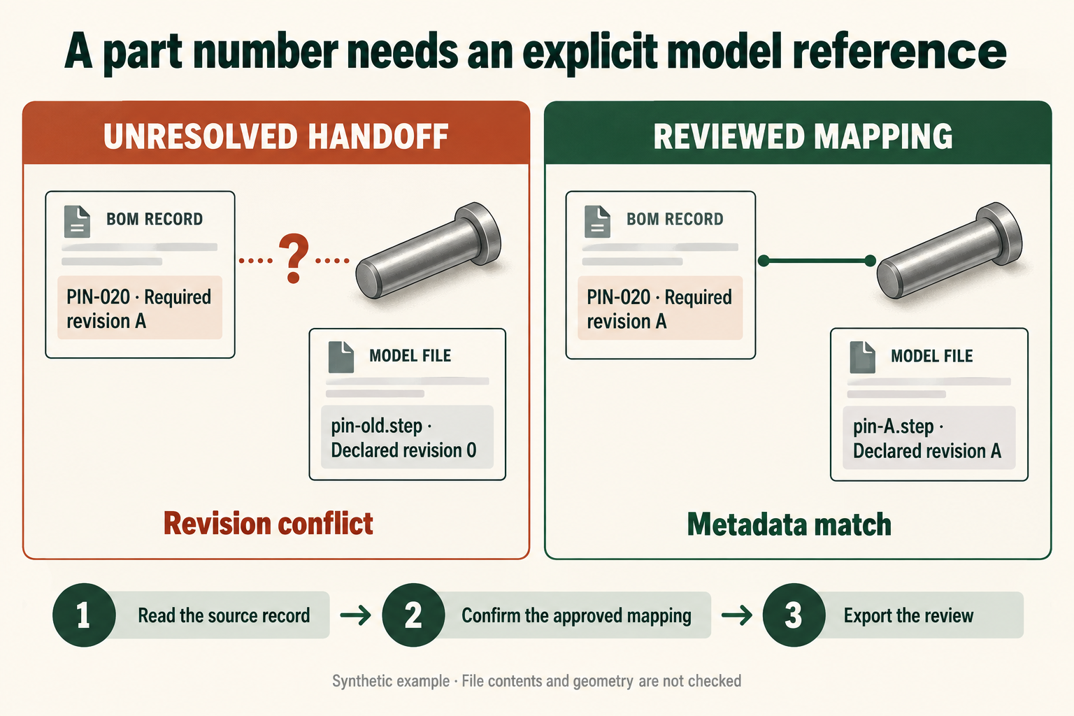
A community question about sharing STEP files with a BOM highlights a separate handoff problem: the recipient needs an explicit relationship between a part and its model. A readable BOM alone does not supply that mapping.
Bring: a BOM CSV with part number and required revision, a model index with part number, exact filename and declared revision, and optionally the files themselves. Check: missing mappings, different revisions, multiple candidates, unused model records and selected-file presence. Take away: an exported review with the source records and unresolved reasons from BOM–Model Check.
- Download the faulty and corrected model-handoff pack, or select Try handoff sample. Expect one metadata match, four records needing review and one unused model record.
- Inspect the evidence: PIN-020 references revision 0 instead of A; VAL-200 has no mapping; SCR-M6 has two candidates; WSH-M6 has no required revision; LEGACY-10 is outside the BOM. Use the row buttons to locate the records instead of choosing the newest-looking filename.
- Apply this exercise’s declared release-owner decisions: PIN-020 uses pin-A.step revision A; VAL-200 uses valve-A.step revision A; SCR-M6 uses screw-a.step; WSH-M6 requires revision A; LEGACY-10 is outside this package. BRK-100 remains revision B. These invented decisions are written in the pack’s README; the checker does not generate them.
- Load both corrected CSVs and rerun. Expect five Metadata match records, with file presence not checked. The pack includes no CAD models. Export the review and verify all five identities and revisions.
- In your own handoff, obtain equivalent decisions from the controlled part master and configuration mapping. Select actual files for the optional presence check, then use the team’s native CAD and release process to verify their contents.
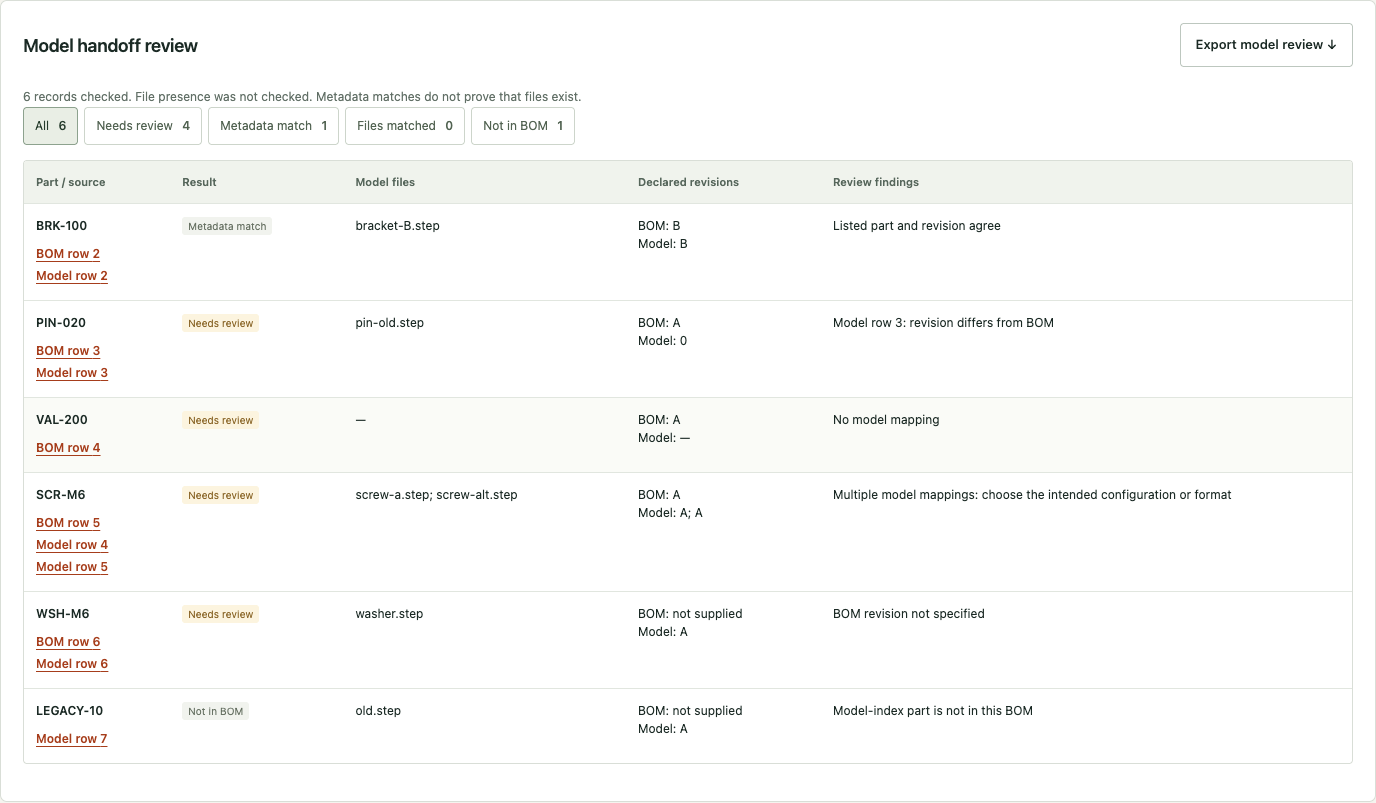
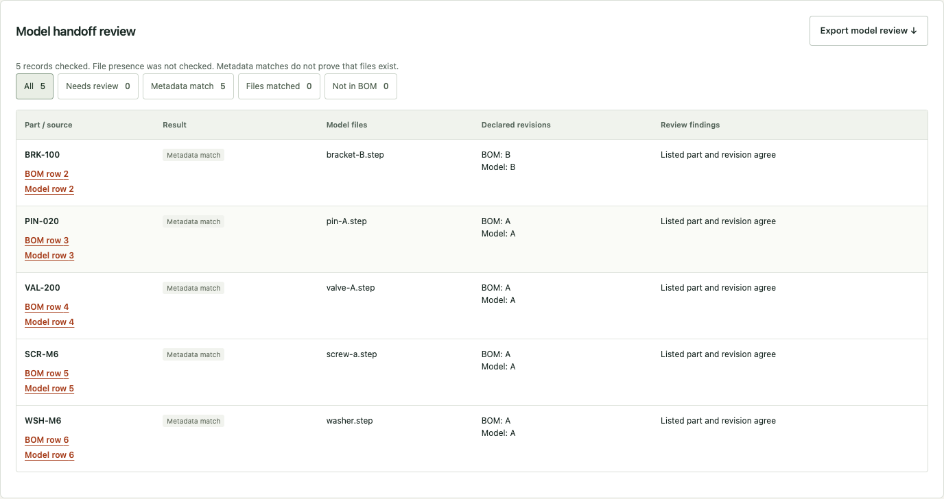
Matching filenames and declared revisions does not prove model geometry, native revision or assembly compatibility. If one part intentionally has several configurations or formats, resolve the package scope explicitly. The model-handoff walkthrough explains file selection, source-record navigation and export. Where process tags are involved, first reconcile the connection table and tag-to-part assignments.
Frequently asked questions
Why does my SOLIDWORKS BOM show the file name instead of the part number?
The configuration's “Part number displayed when used in a bill of materials” option is set to the document name, or the BOM column reads a different property. Check the configuration's properties first, then the column's property source.
How do I show a different part number for each configuration?
Open the configuration's Properties in ConfigurationManager and choose the configuration name or a user-specified name for the BOM part number. You can also drive the value from a configuration-specific custom property mapped to the BOM column.
Why are two configurations combined into one BOM row?
Rows are grouped when the components resolve to the same part number under the table's grouping rules. Give each configuration its own approved part number, or change the BOM's configuration grouping options if separate rows are intended.
What is the difference between a configuration name and a part number?
The configuration name identifies a variant inside the file. The part number is the approved identity your engineering or PDM process controls. They can be the same, but you should decide which field owns the identity before editing the table.
Can I check a BOM exported to CSV against my part master?
Yes. Export the table, keep the file, configuration and displayed part number in the same row, and compare that list to the approved part master. Fix differences at the source property, not by editing cells in the table.
Scope: this example explains identity and display checks. It is not a PDM migration procedure, a purchasing release or proof that a particular component is suitable for a process.
Check the BOM you exported
MST Engineering Intelligence. “SOLIDWORKS BOM Tutorial: Part Numbers and Configurations.” MST Engineering Intelligence. Updated 2026-11-02. https://mst-us.ai/solidworks-bom-part-numbers-configurations/
FOR EQUIPMENT MANUFACTURERS AND DESIGN TEAMS
Talk to the engineering team.
Tell us what your team designs and which repetitive task you want to improve. A short, non-confidential description is enough to discuss a relevant demo. Arrange a private channel with MST before sharing company drawings or models.
Operated by MOORE SOLUTION TECHNOLOGY PTE. LTD. · Singapore UEN 202315239E