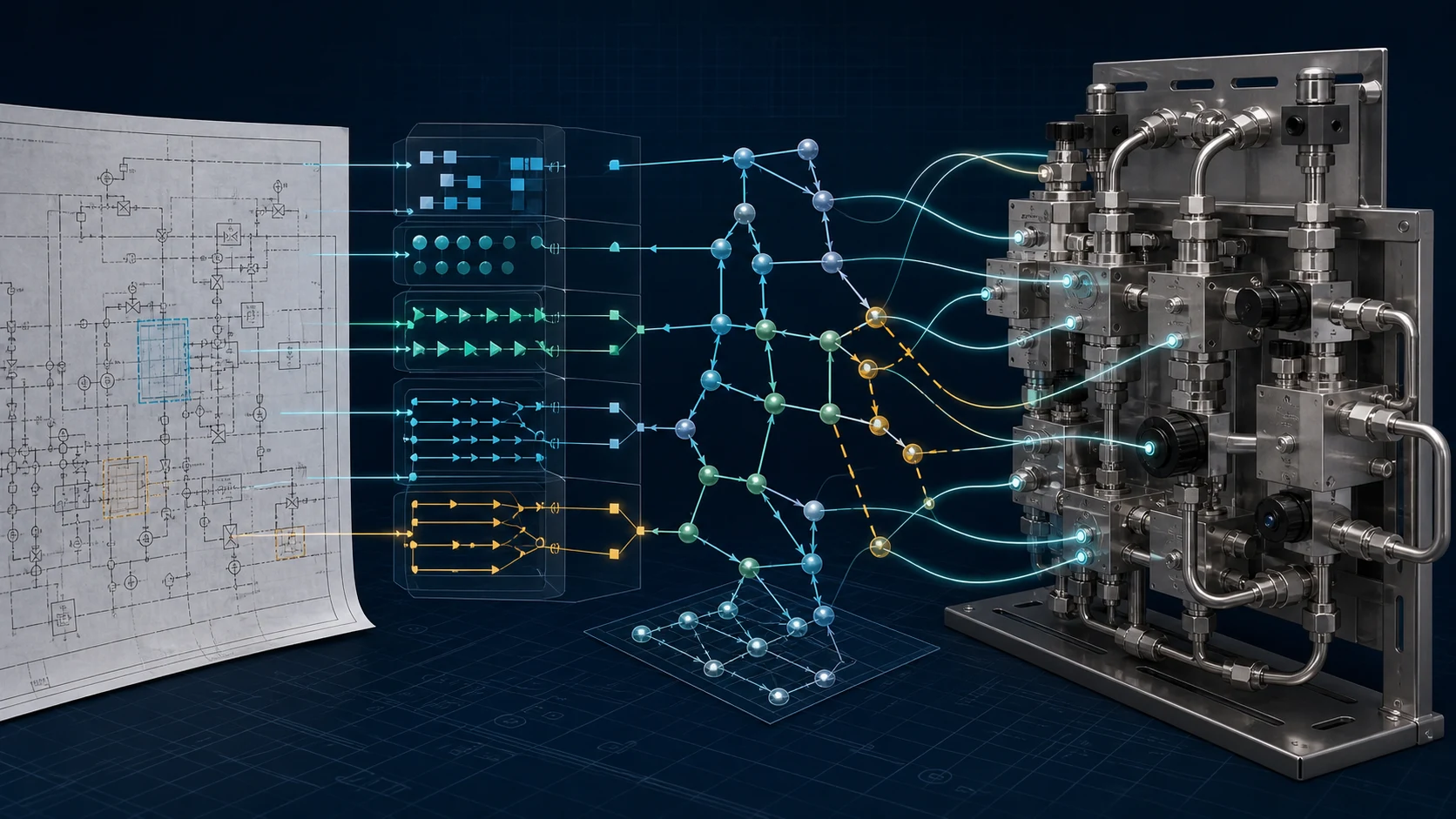
Direct answer: a P&ID connection is not proven by detecting a line or rendering two parts near each other. It is proven only when the source observation, directed engineering relationship, selected physical realization, native SolidWorks components/interfaces and post-execution verdict remain linked.
Stage 1: source-grounded document observations
The input is often a PDF rather than a clean engineering database. Recognition must preserve page, region, symbol, tag, line segment and uncertainty. A later engineer should be able to return to the exact source evidence that produced a topology node or edge.
ISO 10628-1 and ISO 10628-2 describe diagram content, representation and symbols. IEC 62424 addresses process-control engineering requests and exchange with engineering tools. None removes project-specific conventions, drawing quality or revision ambiguity. A production system therefore needs evidence localization and explicit unresolved states, not only a normalized graph.
Stage 2: directed and conditional topology
An undirected “A is connected to B” graph loses material engineering meaning. The intermediate model needs source and destination, device state, bypass or branch semantics, line identity and the conditions under which connectivity exists. The graph is an engineering contract: every edge will later require a physical realization or an explicit exception.
Stage 3: real part and interface truth
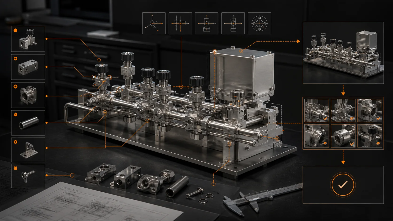
The system should bind customer part numbers to approved native models and identify the physical interfaces that can realize a connection: ports, axes, sealing faces, surface sense, handedness and permitted mate relationships. A visually plausible mesh is not equivalent to a qualified part record. Missing identity or interface truth is a reason to stop.
Stage 4: continuous 3D physical layout
Layout is not a two-dimensional drawing arrangement. It combines discrete choices—part, block, bridge, elbow, plug—with continuous XYZ pose and orientation. It also carries keep-outs, boundary constraints, layer changes and orthogonal routing. Moving a path to another layer creates physical consequences: extra blocks, bridge geometry, elbows, tubing length and BOM changes.
The physical result should exist independently of any particular CAD API as components, interfaces, connections, poses, route tasks and evidence obligations. MST calls this compiler boundary Assembly IR.
Stage 5: native SolidWorks execution
The SOLIDWORKS IAssemblyDoc API exposes assembly operations such as adding components and mate conditions. That API capability is necessary but not sufficient. The engineering problem is deciding which approved component, transform and mate must be executed and why.
The output criterion is a native, editable assembly—not a screenshot, mesh render or animation. The execution worker inserts the approved models, applies deterministic poses/mates, saves the new .sldasm and records the software/input versions used.
Stage 6: reopen and reverse proof
The result must be reopened and interrogated. Component count, part identity, realized mates, rebuild state and interface facts are extracted from the artifact. Each original P&ID edge is then mapped through its physical path to the realized CAD facts. An unproven obligation produces review, fail-closed or cannot-verify—not a silent pass.
W3C PROV-DM provides a general model for entities, activities, agents and derivations. MST’s engineering evidence is domain-specific, but the same provenance principle matters: trust requires knowing what artifact was produced, by which activity, from which identified inputs and under whose authority.
The minimum evidence record
- input file hashes, revisions and approved Rulepack version;
- source observations and unresolved ambiguities;
- topology nodes/edges and conditions;
- part/interface candidates and selection evidence;
- physical solution and Assembly IR version;
- SolidWorks execution facts and output hash;
- obligation-by-obligation verdict and human approval state.
Practice the engineering steps
Start with the first read-only SOLIDWORKS macro, work through assembly mate troubleshooting, and check BOM part numbers and configurations. Each tutorial provides a small task whose result you can inspect.
References
- ISO 10628-1:2014.
- ISO 10628-2:2012.
- IEC 62424:2016.
- SOLIDWORKS API 2026 — IAssemblyDoc.
- W3C PROV-DM.
Limit: the architecture describes MST’s declared product contract. Public evidence for broader part libraries, equipment families and generalization levels must be published separately.
MST Engineering Intelligence. “From a P&ID Edge to Native SolidWorks: What Must Be Proven?.” MST Engineering Intelligence. Updated 2026-09-16. https://mst-us.ai/pid-edge-to-native-solidworks-proof-chain/
CUSTOMERS · PARTNERS · INVESTORS
Talk to the engineering team.
Bring a non-confidential P&ID question, pilot boundary or technical diligence request. Protected engineering material is exchanged only after identity, NDA and scope review.
Operated by MOORE SOLUTION TECHNOLOGY PTE. LTD. · Singapore UEN 202315239E