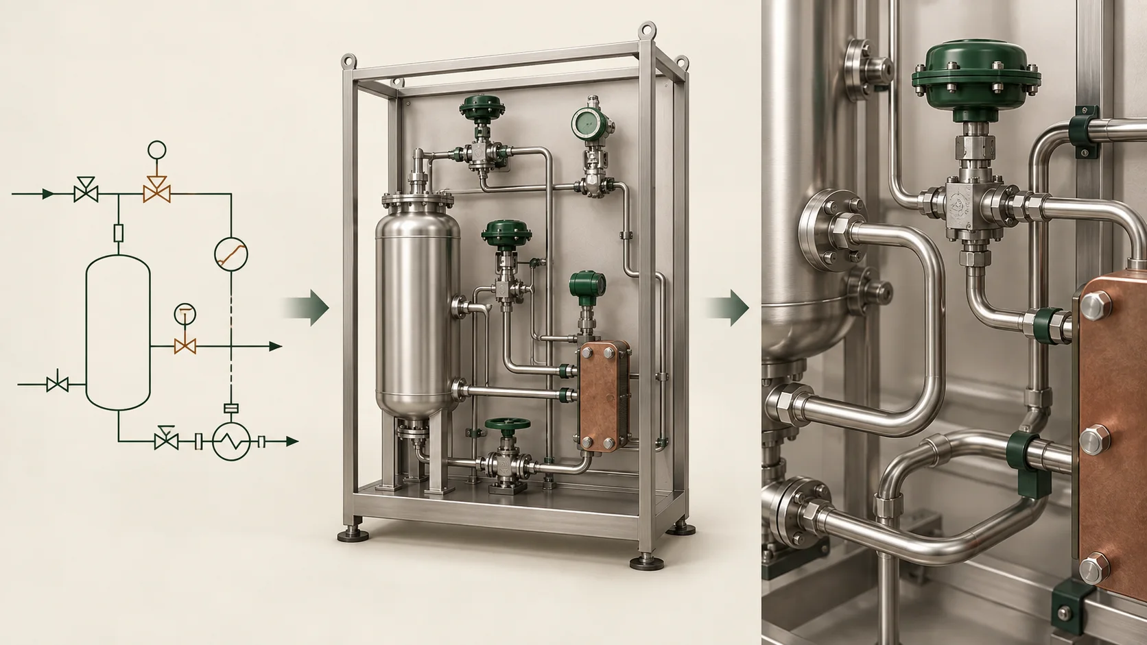
A P&ID tells an equipment team what connects. It leaves another practical question: where can the approved components fit, and how can their ports be connected inside the available space? MST currently uses a workflow that connects these steps: reviewed drawing and BOM inputs, approved component selection and interface data, constrained layout and routing, engineer review, and downstream assembly verification.
Current product workflow and weekly engineering progress · September 27, 2026. The configured P&ID-to-assembly workflow is implemented. The developments described here have different validation scopes; this article does not announce unrestricted public access or completion of every equipment configuration.
Start with connections and approved parts
The input is a reviewed P&ID, a confirmed BOM, an authorized component library, a spatial boundary and customer engineering rules. A valve tag must resolve to a particular component and supported interface. Missing port identities, conflicting parts or unclear connections need a decision before they can become physical design assumptions.
Positions on the P&ID page do not specify installation coordinates. A branch or instrument signal also needs its correct meaning: treating every drawn line as a new process pipe can produce a physically plausible but incorrect system. The engineer reviews these distinctions before layout.
Bind selection and interface facts to the model
For each device, selection must satisfy the approved function, operating range, media, material and connection requirements. The selected part identity and model revision then anchor the process-port and installation-interface data. A similar shape does not establish interchangeability.
Process-port identity, internal connectivity and mounting geometry must remain distinct. A visible hole can be a mounting feature or a blind hole. The connection plan needs evidence of which ports communicate, any directional or device-state restrictions, the matching counterpart, and the required seal or adapter. When these facts are missing, the physical connection remains unresolved.
This is the relationship between a P&ID and the real gas path: the diagram supplies reviewed process intent; approved component information supplies what the selected hardware can connect; layout and assembly must preserve both. The gas-path worksheet exercise shows how to record the mapping and an explicit unknown.
Choose a physical arrangement under declared rules
For supported equipment families, the layout process considers component envelopes, installation planes, space limits, required clearances and allowed interface combinations. It works with the approved parts and customer rules for the task. Changes to placement affect the available pipe routes, so layout and routing must be checked together.
Recent development work has examined a common installation plane for ordinary carrier blocks and their mounted devices, while preserving the separate role of bridge connections. A layout that cannot satisfy the declared boundary or spacing must remain unresolved. A compact-looking arrangement alone is insufficient.

Connect the right ports and inspect the installation chain
The supported routing path uses connection intent, port identity and physical constraints to propose routes. Engineers still need to inspect branches, end connections, clearance and the components that complete each joint. A pressure sensor mounted on a process line, for example, must retain its intended connection and complete mounting chain.
For the supported block-based assembly workflow, that chain includes carrier block, seal and mounted device. Interface geometry and the applicable locating method determine mating relationships. A nearby empty block is not a valid substitute for the carrier required by the process connection.
What this week’s work makes easier to review
- Layout intent: inspect the installation plane and spatial arrangement separately from the connectivity requirement.
- Assembly context: inspect component ownership and subassemblies, and isolate parts when checking a crowded model.
- Rule application: trace the selected customer rules and model versions into the generated task, including cases that remain unresolved.
- Connection completeness: review both interfaces in a mounting chain instead of accepting the presence of a device as proof that it is fully installed.
These are scoped engineering advances. Some pipe connections, model interfaces and complete native-assembly checks remain under validation. Preview geometry and a successful local check do not establish complete equipment acceptance.
How the engineer adjusts the result
The review begins with the source meaning: correct a tag, branch or connection that was interpreted incorrectly. Next verify the selected component and model revision, then the process ports and applicable installation interfaces. For supported configurations, the engineer can review or change the customer rule settings and declared spatial requirements, regenerate the layout, and inspect the resulting component and connection relationships.
Position and orientation must follow the applicable geometry and assembly relationships. The review should explain why a result changed: a corrected connection, another approved part, an interface correction or an allowed constraint change. Moving a displayed component alone does not prove that its gas-path and mating obligations are satisfied.
What should the engineer receive?
A useful review package preserves the input revisions, selected parts, rule version, proposed layout and routes, and unresolved findings. Where the configuration passes the applicable dispatch gates and a SolidWorks executor is available, the downstream path creates an editable native assembly. Its saved result must be reopened and checked against the intended components, mates, connectivity and spatial requirements.
Our existing public demonstration covers the structured-input-to-SolidWorks assembly segment. It should not be read as a new, full recording of every recognition, layout and routing step described here. Supported scope and evidence should be agreed for each pilot.
Try the first review step
Begin with the worked P&ID reading tutorial and P&ID Tag Check. These help reconcile reviewed identifiers; they do not perform physical routing. For the full equipment task, review MST’s layout and routing scope and request a demonstration using a non-confidential description of the component family, available models and required output.
MST original product progress note, reviewed September 27, 2026 against internal implementation and validation records. No customer drawings, model identifiers or performance claims are published. Availability and acceptance depend on the configured engineering scope.
MST Engineering Intelligence. “MST product update: how we turn P&ID connections into a pipe layout.” MST Engineering Intelligence. Updated 2026-09-27. https://mst-us.ai/mst-pid-layout-routing-product-progress/
FOR EQUIPMENT MANUFACTURERS AND DESIGN TEAMS
Talk to the engineering team.
Tell us what your team designs and which repetitive task you want to improve. A short, non-confidential description is enough to discuss a relevant demo. Arrange a private channel with MST before sharing company drawings or models.
Operated by MOORE SOLUTION TECHNOLOGY PTE. LTD. · Singapore UEN 202315239E