
Direct answer: read a P&ID by checking its revision and legend, identifying tagged equipment and instruments, tracing each connection through junctions and continuation references, and recording the conditions that affect flow. A line crossing, a symbol or a familiar tag abbreviation is not enough to establish meaning without the drawing’s conventions.
This beginner exercise produces a small connection worksheet. It is useful before manual equipment design, a design review, or an AI-assisted interpretation.
On this page: open the example drawing, follow three connections, and check your reading.
Start with a drawing you can follow
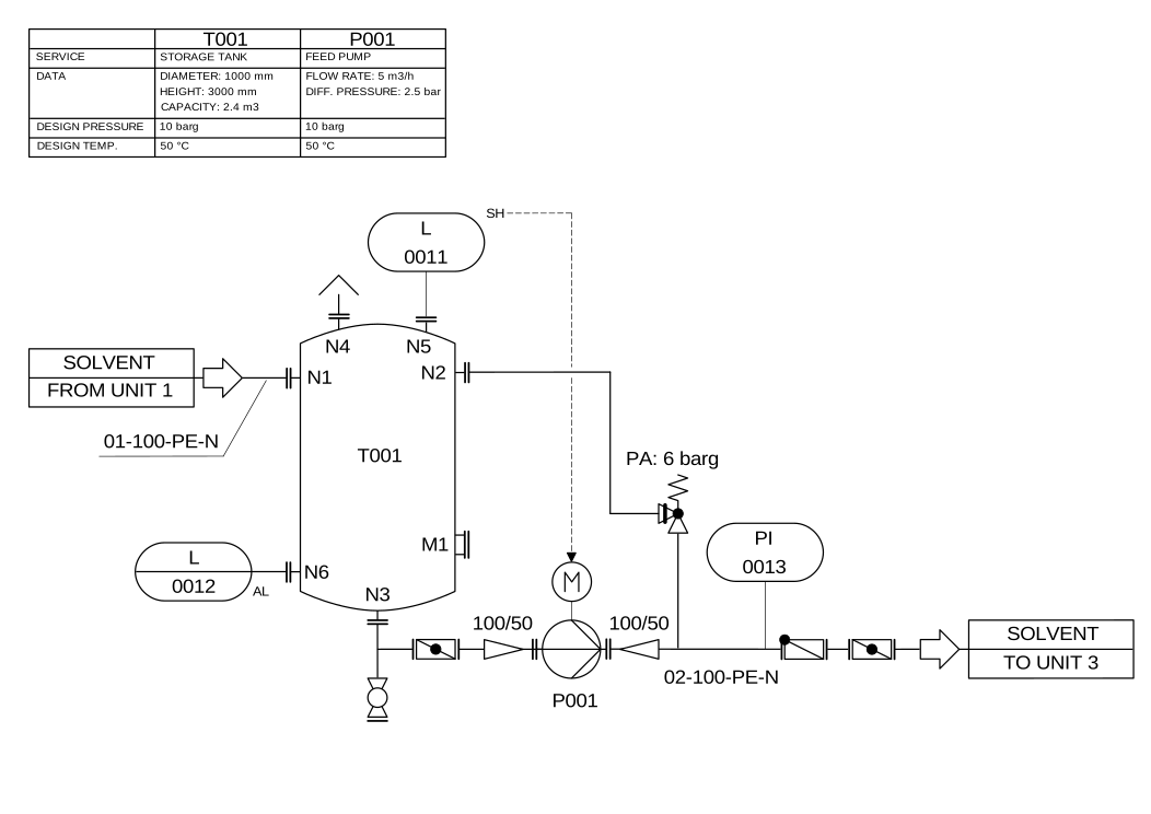

Begin with three visible objects: T001 is the storage tank, P001 is the feed pump, and N1–N6 identify tank nozzles. The small equipment table helps identify T001 and P001. A nozzle label is not a separate equipment tag.
Step 1: establish which drawing you are reading
Record the drawing number, revision, sheet number, title, approval status and the legend or notes that govern it. Keep related sheets and the equipment/instrument lists available. If two sheets have conflicting revisions, identify that conflict before joining their connections.
ISO 10628-1 covers the content and representation of process diagrams. Its scope does not mean every customer PDF follows identical naming or symbols. The project’s approved conventions remain necessary.
Step 2: identify objects using both symbol and tag
For each item, record its visible tag, symbol class, page location and the legend entry supporting your interpretation. Keep uncertain text and uncertain symbol identity separate. A clear tag beside an unclear symbol does not resolve the device type.
Do not copy tag expansions from another plant’s drawing without checking. A letter combination may follow a standard convention, a company convention or a project-specific exception. The worksheet should preserve the original text alongside the interpretation.
Step 3: trace one connection at a time
- Choose one tagged item and follow its process line to the next item or continuation.
- At every crossing, inspect the drawing’s junction convention. Do not automatically connect every intersecting stroke.
- Record line identity and any specification break or annotation affecting that segment.
- For an off-page connector, locate the referenced sheet and matching continuation. Mark it unresolved if either is absent.
- Use explicit arrows and documented process context for direction. Do not infer flow simply because the drawing reads from left to right.
The DEXPI P&ID 1.4 piping-segment model distinguishes items, connections, source/target references and flow-direction information. It is a useful example of why these facts should be recorded separately; this worksheet is not a claim that your PDF is DEXPI-compliant.
Step 4: trace three routes in the example
| Route to locate | What to record | What remains unresolved |
|---|---|---|
| Unit 1 → T001/N1 | Follow the continuous inlet line, its arrow and label 01-100-PE-N. | The upstream equipment beyond this sheet. |
| T001/N3 → P001 inlet | Follow the tank outlet through each intervening symbol; note every branch. | Any symbol meaning that lacks a confirmed legend. |
| P001 discharge → Unit 3 | Follow line 02-100-PE-N to the external boundary; record the return branch separately. | The downstream equipment and operating conditions. |
These are route summaries. In your detailed worksheet, split a route at each identified device or branch. Do not skip the return connection toward T001/N2 simply because you are following the main path.
Next locate the dashed relationship from the level-related item labelled L 0011, with SH beside it, toward the motor. Keep this instrument relationship separate from the solvent pipe sequence. The diagram does not supply a complete control cause-and-effect description.
Step 5: produce a reviewable worksheet
Use columns for source item, destination item, line/tag reference, page location, direction evidence, applicable condition, unresolved question and reviewer. Keep “unreadable,” “not shown” and “contradictory” as different findings. They require different follow-up.
A reviewer should be able to return to the drawing location for every accepted connection. The exercise is complete when each in-scope path is either supported or explicitly unresolved, not when every row has been filled with a guess.
Check your reading before moving on
- Does the dashed instrument relationship add another solvent pipe?
- Does the “TO UNIT 3” arrow identify all downstream equipment?
- Can the return branch be omitted from the connection record?
Show the answers
No to all three. Record the instrument relationship separately; resolve the off-page continuation using its referenced documents; retain the return branch as its own connection. A good reading record preserves uncertainty instead of silently inventing the missing facts.
What a P&ID does not supply by itself
Do not assume it contains all elevations, component envelopes, mating faces, maintenance clearances or a complete mechanical BOM. Those facts must come from the controlled design package before a native assembly can be generated and checked.
Continue with P&ID understanding beyond OCR, part-number and configuration mapping, or the input requirements for a native SOLIDWORKS assembly.
Try a complete illustrated example
Work through the tank-and-pump P&ID exercise, with an attributed full-size drawing. Trace the material path, record its branches, and keep the instrument signal separate from the pipe network.
The drawing and instrument list disagree: which one should change?
A drawing-only tag is a discrepancy to investigate, not automatic proof that equipment must be added. Freeze the two document revisions, normalize only the formatting allowed by the project convention, and preserve identifiers and leading zeros.
- Use P&ID Tag Check with the synthetic sample. Read the text, review every occurrence and load the sample reference.
- Expect XV-104 only in the drawing and TT-103 only in the reference. Check their source revisions and ask the document owner whether they represent an addition, deletion or transcription error.
- PT-101 appears twice in the drawing but once in the reference. Distinguish a repeated graphical occurrence from two physical instruments.
- Export the comparison and assign each unresolved discrepancy to an owner. Verify pipe connectivity, signal meaning and operating conditions separately.
For a repeatable local workflow and supported tag patterns, read the P&ID reconciliation handbook. When the task extends to building a controlled equipment assembly from P&ID intent and approved parts, inspect the MST product scope and demonstration.
Check the connection worksheet against your reviewed tag list
After tracing a drawing, a spreadsheet can still contain a mistyped endpoint, a repeated record or an unassigned device. Connection Table Check compares the records you supply and returns source-record findings you can hand to a reviewer.
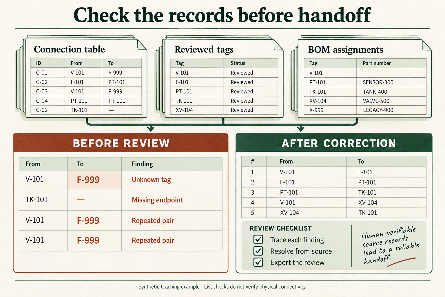
- Bring three explicit inputs. Export a connection CSV with From tag and To tag, a unique reviewed Tag list, and optionally a Tag/Part number BOM assignment table. Connection ID is optional. Resolve repeated graphical occurrences before creating the unique registry; preserve the drawing revision and evidence locations in your controlled worksheet.
- Run a known faulty example. Download the complete exercise pack, or select Try faulty sample in the tool. Confirm the mappings and run the check. Expect five connection records, five reviewed tags and 12 review items.
- Inspect actual records. Eight findings concern the connections: two unknown F-999 endpoints, two rows sharing C-02, two repeated directed pairs, one self-pair and one missing endpoint. The other four concern an unused XV-104 tag, a missing F-101 assignment, a missing V-101 part number and an out-of-registry X-999 assignment. Select any source-record button to locate its input, then export the full review.
- Correct from declared evidence. This synthetic exercise specifies a V-101 → F-101 → PT-101 → TK-101 main chain and a V-101 → XV-104 → TK-101 branch. Its corrected assignment file supplies one part number per tag. Load the corrected sample and rerun: expect zero list discrepancies. The tool has not inferred that branch or approved the process.
- Keep unresolved meaning visible. Repeated tag pairs can represent intentional parallel lines; an external boundary may not require a BOM item. Use line and port records, the drawing and the responsible owner’s scope decision before editing these findings.
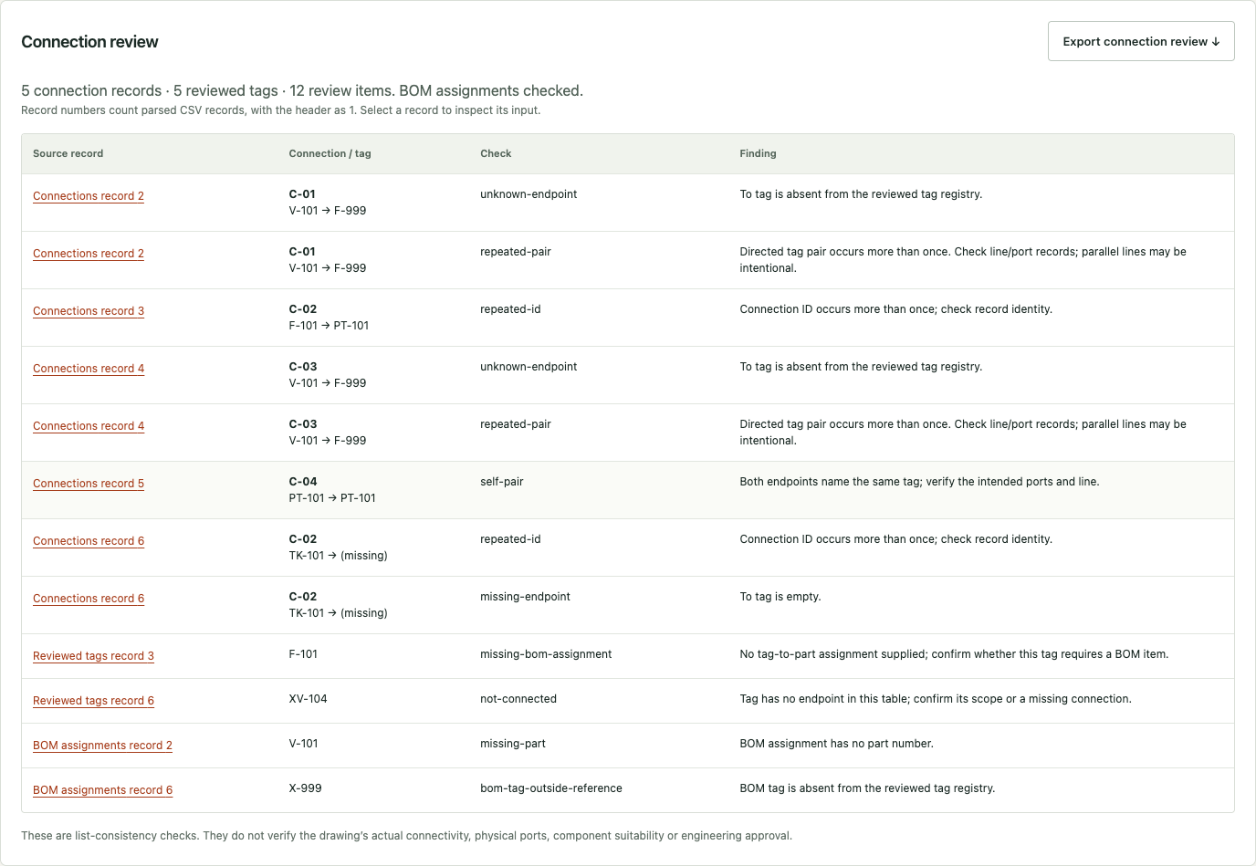

The exercise uses invented identifiers separate from the attributed drawing above. Read the full connection-table walkthrough for individual downloads, expected findings and recovery steps. Matching is case-sensitive after trimming outer spaces; an empty BOM input means assignments were not checked. A clean list cannot establish missing paths that were never entered, physical port compatibility or actual drawing connectivity. Next, use BOM–Model Check to compare the selected parts with the declared model index.
Scope: reviewed 17 September 2026 against the attributed drawing and cited references. This is a reading exercise, not an operating procedure, a universal symbol dictionary or an engineering approval of a real process.
From a P&ID tag to a real gas-path connection
Recognizing a valve symbol establishes only part of the task. To construct a physical gas system, bind each reviewed device to a suitable model and verify its process ports, internal passages, mating interfaces and intended neighbours. The drawing, equipment specification and approved component data each supply different information.
- Interpret the process role. Identify the device, branch, signal and connection evidence in the drawing. Apply its legend. A crossing is not automatically a junction, and an instrument signal is not a process pipe.
- Select a qualified component. Check the function and the project’s required operating range, media compatibility, materials and connection requirements against approved product data. Record the selected part and model revision. A similar-looking CAD model is insufficient evidence for selection.
- Identify the physical ports. Record each process port’s identity, location, axis, connection type and any direction restriction. Distinguish process ports from mounting holes and other geometric features.
- Verify the internal gas path. Establish which ports communicate under the relevant device state. Geometry alone may not reveal an internal passage, seat or blind hole. Use approved component information and engineering confirmation when that evidence is absent.
- Complete the connection interface. Check the counterpart, required seal or adapter, contact and locating features, and assembly rules. A correct pair of coordinates cannot compensate for incompatible interfaces or a missing seal.
- Lay out and route, then compare back. Preserve the reviewed connectivity while satisfying spatial and installation requirements. Compare the intended endpoint pairs with the actual assembled connection chain and record unresolved connections separately.
A small exercise with an explicit unknown
Suppose a synthetic drawing specifies IN → V-101 → F-101 → OUT. Its approved component list identifies V-101 as a valve and F-101 as a flow-control device. The available valve model has three visible holes, but the supplied component record identifies only two process ports.
The expected decision is to map the two documented ports to the intended upstream and downstream connections, then leave the third hole unclassified until its role is established. Do not create a new branch or assume the third hole is connected internally. If the documented port identities cannot be bound to the selected model revision, keep the physical connection unresolved.
Build a connection worksheet containing: drawing revision; tag; required function; selected part and model revision; upstream and downstream process ports; internal-passage evidence; mating interface; seal or adapter; counterpart; evidence source; reviewer decision. This lets an engineer locate the missing evidence instead of repairing an unexplained 3D result.
Product fit: P&ID Tag Check helps reconcile reviewed identifiers only. MST’s configured equipment workflow also uses approved component models, interface rules, physical layout and downstream assembly checks. New model families and uncertain internal connections require qualification; a free tag comparison cannot establish these facts. Read the current product progress and layout walkthrough for the broader scope.
Connect the diagram review to the equipment
MST Engineering Intelligence. “How to Read a P&ID: Symbols, Tags and Connections.” MST Engineering Intelligence. Updated 2026-10-27. https://mst-us.ai/how-to-read-a-pid/
FOR EQUIPMENT MANUFACTURERS AND DESIGN TEAMS
Talk to the engineering team.
Tell us what your team designs and which repetitive task you want to improve. A short, non-confidential description is enough to discuss a relevant demo. Arrange a private channel with MST before sharing company drawings or models.
Operated by MOORE SOLUTION TECHNOLOGY PTE. LTD. · Singapore UEN 202315239E