
An under-defined SOLIDWORKS sketch still has geometry that can move or change size. Find the remaining freedom, then add the dimension or relation that expresses your design intent. In this exercise, you will constrain a circle by controlling its centre and diameter, and verify the result by changing one intended dimension.
Use a new practice part. Keep a note of your SOLIDWORKS version and unit system so the exercise is repeatable.
Jump to: the three-state illustration, the symptom checklist, or the final check.
Why a diameter does not locate a circle
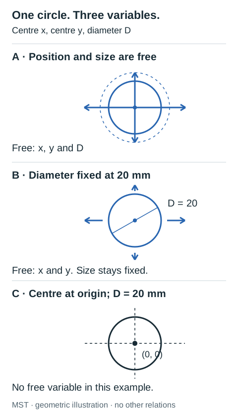
The circle has a horizontal centre coordinate, a vertical centre coordinate and a diameter. A diameter dimension fixes size, leaving two position variables. Making the centre coincident with the fixed origin removes those two freedoms. This explains why adding a size dimension alone can leave a sketch under defined.
1. Create a deliberately simple sketch
Start a sketch on the Front plane and draw one circle away from the origin. Do not place the centre on another point or line. Automatic relations can still be added while drawing, so inspect the relations that actually exist before proceeding.
Use the status bar and the geometry’s state to inspect the sketch. In the default colour convention, under-defined entities appear blue and fully defined entities black. Colour settings and selection highlighting can differ; the displayed status and relation list are the stronger checks.
The official Sketch Geometry Status guide includes real interface examples of the different states. Use it as the visual reference for your installed version.
2. Separate size from position
For this isolated circle, ask three questions: where is the centre horizontally, where is it vertically, and what is the diameter? A diameter dimension answers only the third question.
- Add a diameter dimension of 20 mm. This is an invented teaching value.
- Try moving the circle’s centre in the practice sketch. If no position relation was added, it should still be free to move.
- Choose the intended design: a circle centred on the origin, or a circle offset from it. Those are different constraint choices.
If the circle does not behave as expected, inspect existing relations first. An automatic coincident relation or a Fix relation may already constrain it.
3. Add the intended position constraint
For the origin-centred version, select the circle centre and the sketch origin and add a coincident relation. Together with the diameter, that should define this simple circle. For an offset version, use horizontal and vertical dimensions from the origin instead, with explicit teaching values such as 30 mm and 15 mm.
Record which design you chose. Making the centre coincident and also demanding nonzero offsets describes conflicting intentions. Similarly, a Fix relation can stop motion without making the intended origin or dimensional relationship clear to the next engineer.
Open Display/Delete Relations to inspect the relation attached to the centre. Confirm that you constrained the centre point you intended, rather than an unrelated piece of geometry.
4. Verify the result with a controlled change
Change the diameter from 20 mm to 24 mm. The centre should remain at its intended location while the size changes. Restore 20 mm and verify the sketch status again. Save your practice file with a name that identifies the chosen case.
A sketch can be fully defined and still describe the wrong design. The useful result is both a solved sketch and predictable behaviour under the changes the design is supposed to allow.
5. Diagnose a sketch that remains under defined
| Observation in the practice file | Check next |
|---|---|
| Circle size stays fixed but its centre moves | Inspect the centre’s position relations or horizontal/vertical locating dimensions. |
| A shown dimension changes when you drag | Check whether it is a driven measurement rather than a driving dimension. |
| The main profile looks defined, but sketch status is not | Inspect construction geometry, loose endpoints and imported or duplicated entities. |
| Adding one relation creates an over-defined state | Read the existing relations and dimensions for a conflict or redundancy before removing anything. |
A line or point can look coincident with another without having the intended relation. Check the relation record and the sketch status; screen position or colour alone is insufficient. See the official sketch status conventions.
Fully Define Sketch can calculate additional dimensions and relations for selected entities or the entire sketch. Review its proposed datums and relationships against your intention before accepting them. Automatic completion is most useful when you understand what the result should mean.
Final check: which change should still be possible?
For the origin-centred circle, try to drag the centre, then edit the driving diameter from 20 mm to 24 mm. Write the expected result before performing the two actions.
Show the expected result
Dragging should not relocate the centre. Editing the diameter should change the circle’s size while keeping the centre at the origin. Fully defined means the current dimensions and relations determine the geometry; it does not mean you can never edit a driving dimension. If your result differs, inspect automatic relations and the selected entities before continuing.
Continue and consult the official illustrations
Continue with assembly mate troubleshooting to apply the same reasoning to components. Use the configuration and BOM tutorial when different design variants must retain clear identities.
- Sketch Geometry Status, including illustrated states.
- Fully Define Sketch PropertyManager and illustrated dimension schemes.
- Fully Defined Sketches overview.
Reviewed against official documentation on 17 September 2026. This exercise was not executed in a SOLIDWORKS session for this publication; use the stated observations to verify it in your installed release.
MST Engineering Intelligence. “SOLIDWORKS Under-Defined Sketch Tutorial: Find the Missing Constraint.” MST Engineering Intelligence. Updated 2026-09-17. https://mst-us.ai/solidworks-under-defined-sketch-tutorial/
CUSTOMERS · PARTNERS · INVESTORS
Talk to the engineering team.
Bring a non-confidential P&ID question, pilot boundary or technical diligence request. Protected engineering material is exchanged only after identity, NDA and scope review.
Operated by MOORE SOLUTION TECHNOLOGY PTE. LTD. · Singapore UEN 202315239E