A process branch on a P&ID may contain only a few symbols. In a dense equipment assembly, finding the corresponding valves, flow controllers and connections can take much longer. Repeated channels make that task harder: similar-looking components can belong to different branches.
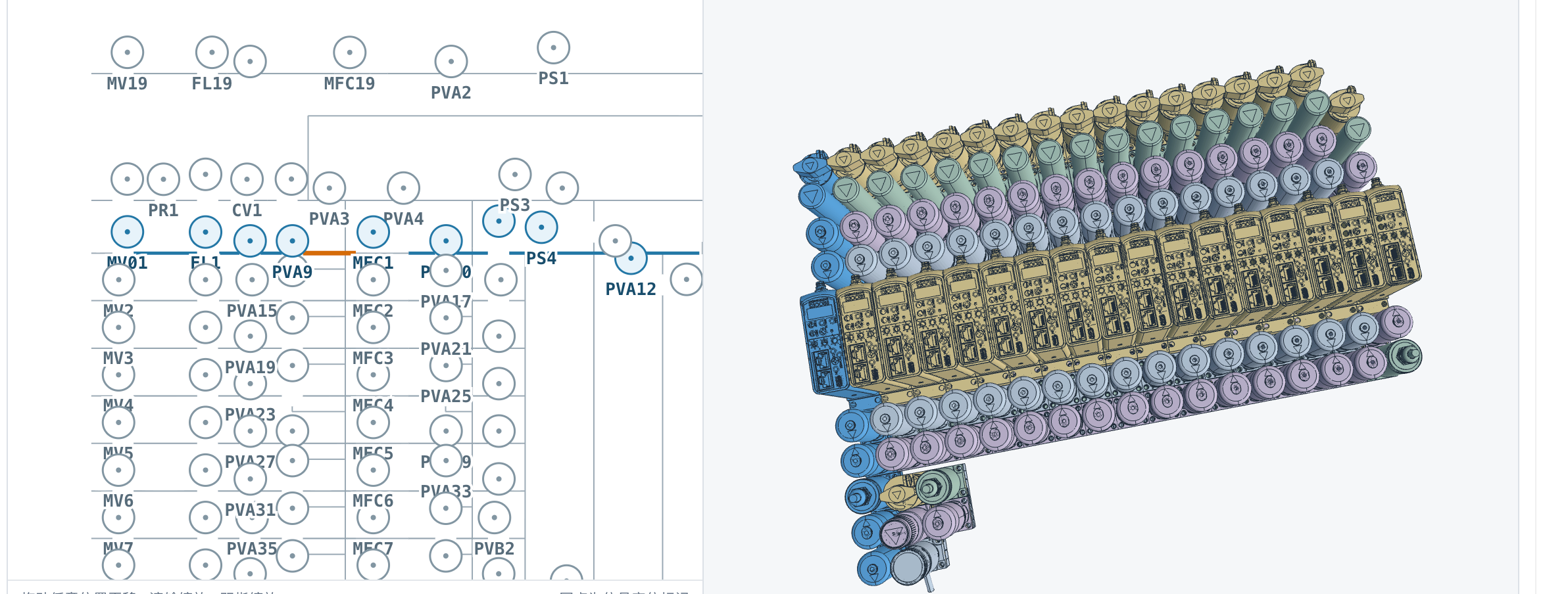
MST connects the two views. Select a branch in the P&ID-derived topology on the left, and the corresponding 3D assembly is displayed on the right. The screenshot below shows this interaction in our equipment workflow. It gives the engineer a practical starting point for checking whether the physical assembly matches the intended process.
From a selected branch to its physical equipment

The left panel is a topology view of tagged components and their connections. The right panel shows the equipment arrangement. The connection between them helps the engineer move from a process question—“Which equipment implements this branch?”—to the relevant physical parts.
That matters when several channels use similar components. An engineer can focus the review on the selected branch, inspect its components in context and compare the result with the intended connection sequence. A visual highlight provides orientation; the review still needs to check part identity, interfaces and connectivity.
The engineering problem starts before 3D assembly
Equipment engineers often begin with a previous assembly, approved parts and a new set of requirements. They reuse what still fits, replace components, add or remove branches, and rearrange the equipment within the available space. The work is not simply creating another 3D picture. It is keeping the process requirements, chosen hardware and physical arrangement consistent as the design changes.
A useful AI workflow therefore needs to carry information through several connected tasks: interpret the P&ID, establish the topology, resolve component selection, build the assembly and make the result inspectable. An error in an early connection can otherwise become a convincing-looking model that implements the wrong process.
Recognize the P&ID and preserve its connections
Reading a tag is only one part of interpreting a P&ID. The next task needs to know which components connect, where branches split or join, and which lines represent process connections or instrument signals. The position of a symbol on the drawing does not specify where that component should be installed in 3D.
For engineering use, recognition should produce a topology the engineer can inspect against the source drawing. Unclear symbols, missing tags and ambiguous crossings need to remain visible as unresolved items. Silently guessing a connection shifts the error into component selection and assembly, where correction becomes more expensive.
Our worked P&ID reading guide explains the first review step. The linked topology-and-assembly view shown here addresses the next question: where did that reviewed branch appear in the equipment?
Connect component selection to the model being assembled
A P&ID symbol describes a function; it does not, by itself, establish a complete purchase specification. Selection also depends on operating conditions, media compatibility, material, connection type and the customer’s approved component range. The selected item must resolve to the correct model and revision before assembly.
MST’s configured workflow works with reviewed inputs and an authorized component library. Within that agreed scope, the selection and assembly task can use approved parts and their interface information. A similar shape or a matching name alone is insufficient evidence that two components are interchangeable.
The result should let an engineer answer three concrete questions: which part was selected, why it fits the requirement, and where that part appears in the assembly. Missing information needs an engineering decision rather than an invisible default.
Keep the P&ID-to-3D correspondence available for review
Correspondence is not always one symbol to one CAD part. A device can be represented by a subassembly. A process connection can require multiple physical items. Mounting hardware and support structures may be necessary even when they do not appear as separate process symbols.
A useful check therefore follows the engineering relationship. Does this branch contain the intended devices? Are the selected models correct? Do the relevant ports connect in the intended order? Are the additional items needed to complete those connections present?
The branch-selection interaction makes the relevant assembly easier to locate. It does not, on its own, establish that every connection, clearance or operating requirement has passed. The screenshot demonstrates the correspondence view; the acceptance checks depend on the equipment configuration and the available engineering data.
Give the engineer a focused review, with a clear revision
The goal is a coherent review of the generated result. The engineer should be able to move through the branches, confirm the selected components, inspect the physical connections and record the decisions that complete the design.
- Process: confirm that the interpreted branches match the reviewed P&ID.
- Selection: check approved part identities, revisions and required interfaces.
- Assembly: inspect arrangement, connection completeness and the applicable spatial requirements.
- Open items: resolve missing information and keep any remaining exceptions visible.
Approval applies to a particular set of inputs and an assembly revision. If a branch, component or requirement changes, the affected relationships need review again. “Review once” is useful as a goal for a complete revision; it cannot mean that future changes inherit approval automatically.
What makes the workflow worth using?
For an equipment team, the value is the work saved between the process drawing and a reviewed assembly. That includes locating the right parts, placing and connecting them, checking correspondence and correcting mistakes. Generation speed is only one part of that total.
MST’s Mechanical Assembly AI provides a configured path toward native, editable SOLIDWORKS assemblies for supported equipment tasks. The published assembly recording demonstrates one segment of that workflow. The screenshot in this article shows the linked topology-and-3D review interface; it is a separate example, not a recording of the complete recognition-to-delivery process.
A useful pilot starts with one representative equipment configuration, an approved component library and agreed acceptance checks. Compare the existing process with the assisted workflow, including engineering review and correction time. The result should be an assembly the team can inspect, revise and continue working on.
Watch the native assembly demonstration, or request a demonstration for your equipment workflow. Start with a non-confidential description of the equipment, available component models and required output.
MST original engineering article, October 1, 2026. The screenshot is an actual MST interface; the branch-selection behavior was confirmed by the product team. It illustrates the correspondence review described here and does not establish an accuracy benchmark or unrestricted coverage of P&ID formats and equipment configurations.
MST Engineering Intelligence. “P&ID to 3D assembly: select a branch, inspect the equipment.” MST Engineering Intelligence. Updated 2026-10-01. https://mst-us.ai/pid-to-3d-assembly-branch-review/
CUSTOMERS · PARTNERS · INVESTORS
Talk to the engineering team.
Bring a non-confidential P&ID question, pilot boundary or technical diligence request. Protected engineering material is exchanged only after identity, NDA and scope review.
Operated by MOORE SOLUTION TECHNOLOGY PTE. LTD. · Singapore UEN 202315239E