
Working on AI for mechanical design has made one thing increasingly clear to me: a goal may take one sentence to describe and a great deal of careful work to realize.
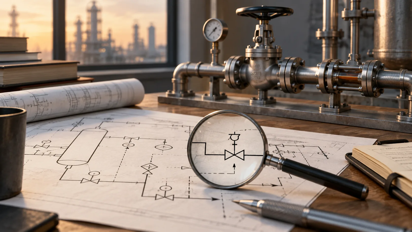
Consider a P&ID. We want a system to understand its equipment, piping and connections, then use that information in equipment design. A piping and instrumentation diagram describes relationships between process equipment, instruments, fluid flows and control signals. These are also the information and relationships addressed in Microsoft’s P&ID digitization project.
The question I keep returning to is how drawings from different sources, with different conventions and occasional ambiguities, can produce information that the next engineering task can actually rely on. A useful result within a supported scope matters. Extending that capability to new drawing conditions and equipment families requires its own validation.
The same document type can contain different conventions
Drawing sources differ in their legends, annotation practices and file quality. Standards provide a foundation, while the conventions of a particular project still need to be understood. Microsoft’s project account identifies symbol variability, similar shapes and low-resolution images as recognition challenges.
An unfamiliar symbol raises several questions. Which convention applies? Does the legend explain it? Which object does the nearby text identify? Does the surrounding context change the interpretation?
Recognizing a familiar drawing is valuable progress. Assessing how reliably that progress carries over requires a wider range of input conditions. Connecting a customer’s existing models, accommodating a different drawing convention and adapting to a new equipment family are distinct tasks. They should be evaluated separately.
Recognized objects still need the right relationships
An engineering drawing describes objects and their relationships. A graph represents that structure through objects and connections.
Recognizing a valve leaves further questions: which line connects to it, which equipment is adjacent, which tag belongs to it and where an off-page connection leads. When two lines cross on the page, the drawing convention determines whether they connect.
Microsoft’s account discusses text association, line detection, intersections and direction. These issues matter because a wrong critical connection can misrepresent the system even when many individual components have been recognized correctly.
In my view, an object-detection demonstration describes one part of the capability. The relationships need their own examination.

Measure individual predictions and complete tasks separately
Before discussing accuracy, we need to define what is being measured: text, symbol classes, connections or all critical information in a drawing. P&ID graph-extraction research evaluates symbols, nodes and edges separately. Stürmer and colleagues, metrics and results
A mathematical illustration helps. Suppose a drawing contains 500 decisions that must all be correct. If each decision is correct with probability 99.9%, and the decisions are independent, the probability that all are correct is approximately:
0.999^500 ≈ 60.6%.
This is an illustration, not an MST benchmark. Real engineering errors need not be independent. It shows why complete-task reliability deserves a separate evaluation.
Consequences also differ. An inconsequential note and a wrong critical connection can have very different effects on later design. Alongside average metrics, I want to know what is missing, which relationships need confirmation and how easily an engineer can locate and correct an error.
Particular attention belongs to errors that might be treated as established facts by subsequent design work.
Drawing facts and new design decisions have different foundations
Understanding a P&ID still leaves physical design decisions to make. The same research notes that line lengths on a P&ID do not necessarily correspond to actual pipe or component lengths. The positions and lines on the page cannot uniquely determine a physical arrangement. Research discussion
Moving into equipment layout involves both extracting information already expressed in the drawing and making decisions under additional equipment parameters, space requirements and design constraints.
I believe their foundations need to remain clear. Information explicitly present in the source should be checkable. Missing conditions should be visible. A proposed arrangement should make its assumptions understandable. Engineers should be able to distinguish source information from a subsequent design judgment.
Count the work of review when evaluating automation
AI can become useful within a defined scope and a concrete engineering task, then expand through further validation. File quality, drawing conventions and necessary inputs belong in that evaluation. Missing or conflicting information should remain visible to the person using the result.
Engineering rules can help check particular problems, provided their coverage is clear. Critical information also needs appropriate engineering review; a model’s own confidence is insufficient to decide everything worth checking.
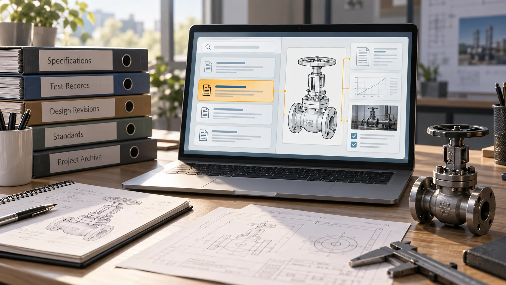
Adding a review step still leaves an important question. If engineers must reread the whole drawing and reconstruct every relationship to trust the output, how much work has the automation actually saved?
I want delivery evaluations to include preparation, checking, correction and final confirmation. They should also assess whether errors are easier to find and previous experience is easier to reuse. An already supported equipment family and the first adaptation to a new family should have separate workload records.
These practical measures help determine whether a system is becoming a dependable tool for engineering teams.
Careful thought and sustained attention still matter
The longer I work on this problem, the more I think mechanical-design AI needs to be discussed through data understanding, engineering constraints and verification as well as generation.
Reducing manual work means counting the work of checking. Increasing automation also means making unresolved questions visible. Useful progress should give us a clearer understanding of the basis for a result, what can be trusted and what still needs confirmation.
AI can help us try ideas faster. Understanding the problem and testing the details still require sustained attention. In the AI era, careful thought and focus continue to shape whether an engineering tool can be delivered and used with confidence.
Source notes
Microsoft ISE Developer Blog, Engineering Document P&ID Digitization, February 9, 2024.
Stürmer and colleagues, From Engineering Diagrams to Graphs: Digitizing P&IDs with Transformers, arXiv:2411.13929, version 3, December 19, 2025.
MST original engineering perspective. The probability calculation is illustrative, not an MST benchmark. Reviewed September 21, 2026.
MST Engineering Intelligence. “AI in mechanical design: from reading P&IDs to reliable delivery.” MST Engineering Intelligence. Updated 2026-09-21. https://mst-us.ai/ai-mechanical-design-pid-reliable-delivery/
CUSTOMERS · PARTNERS · INVESTORS
Talk to the engineering team.
Bring a non-confidential P&ID question, pilot boundary or technical diligence request. Protected engineering material is exchanged only after identity, NDA and scope review.
Operated by MOORE SOLUTION TECHNOLOGY PTE. LTD. · Singapore UEN 202315239E