
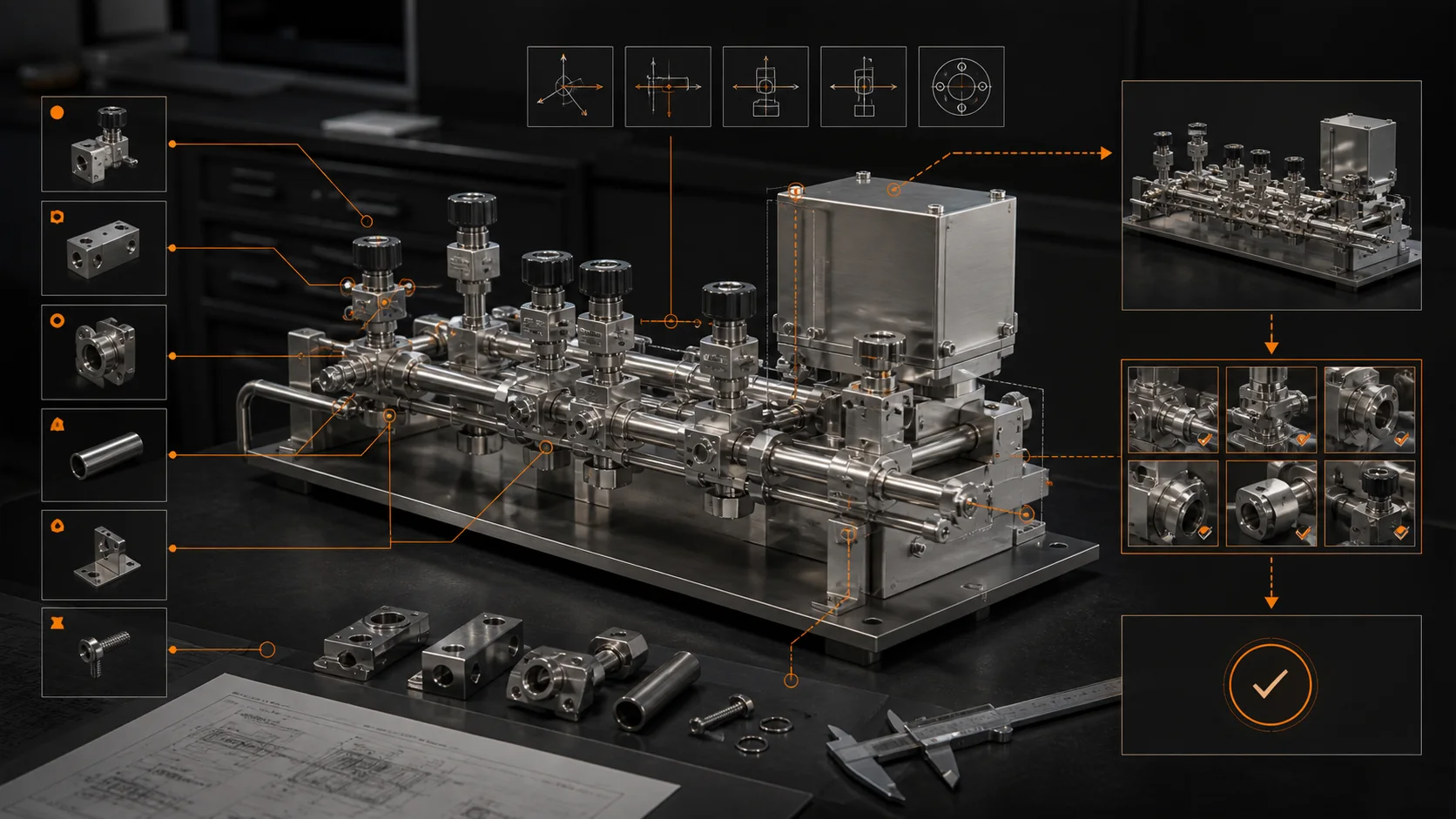
When a STEP file opens in SOLIDWORKS, first check units, body types and external-link settings. Then inspect any faulty faces or gaps using Import Diagnostics. A model that looks complete on screen still needs geometric and dimensional checks before you use it in an assembly.
This tutorial produces an import review record: source file, settings, initial findings, repairs attempted, unresolved issues and final measurements.
Jump to: STEP imported as surfaces instead of a solid, or gaps that Import Diagnostics cannot heal.
1. Preserve the received file and record the import settings
Work with a copy of a non-confidential sample file. Record the supplier or sample source, filename, revision and expected units. If an existing project controls that component’s release, keep the received file intact and create a separately named working result.
Before opening it, inspect Tools → Options → System Options → Import. The available choices depend on the selected format and whether 3D Interconnect is enabled. Record the unit source and link settings actually used; do not assume every installation imports the same file identically.
The official import-options reference explains the settings and when groups of options become available.
2. Inspect what was created
After opening the file, inspect the FeatureManager tree. Record whether the result is an assembly, a part with solid bodies, a part with surface bodies, or another supported representation. Count the relevant bodies or components and compare them with the intended source deliverable.
Measure at least one known feature before attempting assembly work. For a deliberately simple practice model, use a documented 10 mm feature and check the displayed value and unit system. A visually plausible shape is not evidence that its scale is correct.
Imported geometry also does not automatically restore the original author’s native sketches, feature history, mates or design intent.
3. Open Import Diagnostics and record the initial findings
When SOLIDWORKS offers an import-diagnostics prompt, you can start there. For a supported imported part, the documented menu route is Tools → Evaluate → Import Diagnostics. Record the displayed faulty-face and gap counts before changing the model.
If the command is unavailable, inspect the selected object, document type and import route. A live 3D Interconnect relationship can affect the available workflow. Breaking a link changes how the model relates to its source, so understand that consequence and work on a copy before choosing it.
The official diagnosing-and-repairing tutorial provides the corresponding example images and follow-on steps.
4. Repair in small, reviewable steps
Inspect an identified problem in the graphics area before attempting a repair. If you use the available healing command, compare the resulting faces, edges and body classification with the original observations. Keep unresolved items visible in your record.
Import Diagnostics can repair surface and boundary problems, close some gaps and form a solid from a closed surface body. Those operations can change geometry. A lower error count does not establish that a critical sealing face, hole or interface still satisfies the design requirement.
If the defect cannot be resolved confidently, retain the received geometry and request a corrected export or qualified CAD review. Do not invent missing engineering geometry simply to obtain a solid body.
Why did my STEP file import as surfaces instead of a solid?
First confirm that the source is supposed to describe a closed volume. Some supplied surfaces are intentional. For an expected solid, inspect the imported body’s faulty faces and gaps: a shape can look closed while adjacent boundaries do not meet.
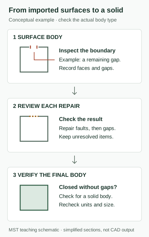
- Record the Surface Bodies and Solid Bodies counts in the imported part, plus the expected source body count.
- Use Import Diagnostics to locate faulty faces and boundary gaps. Select a reported item to see the affected geometry before attempting repair.
- Recheck the body type after accepting the diagnostic result. The official overview explains that a closed surface body without gaps can be converted to a solid when the dialog is accepted.
Saving the result as a native part does not by itself prove that surfaces became a solid. Record the body classification, then repeat the dimension and interface checks below.
What if Import Diagnostics cannot heal all gaps or faces?
Keep the unresolved items in the review record. The Import Diagnostics PropertyManager documents a sequence of trying the overall repair, then reviewing faulty faces before remaining gaps. Inspect the selected location and the resulting geometry after each operation.
Stop when the source does not establish the intended missing shape. A filled opening can remove a real design feature. Compare with the supplier’s definition, request a corrected export where necessary, and preserve the received file. Fewer diagnostic faults alone do not establish that a sealing surface or assembly interface is correct.
5. Recheck dimensions and the intended interface
- Repeat the known-feature measurement and verify units.
- Inspect the final body count and any remaining diagnostic findings.
- Check the faces and axes intended for mating, using the component’s actual interface definition.
- Save a separate native working file, reopen it and confirm the required references remain available.
- Record each unresolved item and who must decide whether the import is acceptable.
Your output is an accepted or unresolved import review, with evidence for the decision. It is not a manufacturing-release decision based only on the software reporting no remaining diagnostic errors.
Continue and verify the references
Use mate troubleshooting for the next assembly step, and the component-list API exercise to inspect occurrence identities.
Import troubleshooting documentation reviewed 6 October 2026. No imported CAD file was repaired in a SOLIDWORKS session for this publication. Menu availability and repair results must be checked with your release and sample.
Prepare the checked component for reuse
MST Engineering Intelligence. “SOLIDWORKS STEP Import Tutorial: Diagnose Faces, Gaps and Units.” MST Engineering Intelligence. Updated 2026-10-06. https://mst-us.ai/solidworks-step-import-diagnostics/
FOR EQUIPMENT MANUFACTURERS AND DESIGN TEAMS
Talk to the engineering team.
Tell us what your team designs and which repetitive task you want to improve. A short, non-confidential description is enough to discuss a relevant demo. Arrange a private channel with MST before sharing company drawings or models.
Operated by MOORE SOLUTION TECHNOLOGY PTE. LTD. · Singapore UEN 202315239E